
Temperature Control Method Based on Passive Variable Thermal Resistance

A temperature control method and technology of thermal resistance, which are applied in the direction of temperature control, temperature control by electric means, auxiliary controller with auxiliary heating device, etc. Poor controllability and responsiveness

Inactive Publication Date: 2020-10-23
QINGDAO UNIV
View PDF9 Cites 0 Cited by
  • Summary
  • Abstract
  • Description
  • Claims
  • Application Information

AI Technical Summary

Problems solved by technology

There are at least the following technical defects: adjusting the thermal resistance is not used for real-time temperature control, but only uses the thermal resistance to achieve the initial temperature state of the refrigerator at the set temperature, and applies thermal resistance adjustment to different temperature states of the refrigerator, while real-time temperature control It depends on the fine-tuning of the heater; in the specific temperature control route, only the absolute temperature state of the temperature fluctuation of the refrigerator itself is considered, and the thermal inertia, inertia, and inevitable factors of temperature change rate and change trend that affect the temperature control accuracy are not considered; the intermediate thermal Resistors adopt two methods of mechanical and thermal fluid, the controllability and response ability are extremely poor, and it cannot meet the technical requirements of real-time temperature control, and it is not and impossible to be designed for real-time temperature control; it requires a certain amount of power supply and consumes energy , generating an additional source of interference; applied and limited to the low temperature field

Method used

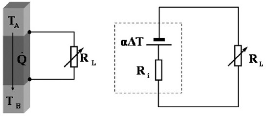

Image

  • Temperature Control Method Based on Passive Variable Thermal Resistance
  • Temperature Control Method Based on Passive Variable Thermal Resistance
  • Temperature Control Method Based on Passive Variable Thermal Resistance

Examples


Embodiment Construction

[0018] In order to make the purpose, technical solution and advantages of the present invention clearer, the present invention will be further described in detail below in conjunction with the accompanying drawings and embodiments. It should be understood that the specific embodiments described here are only used to explain the present invention, not to limit the present invention.

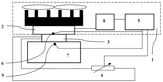
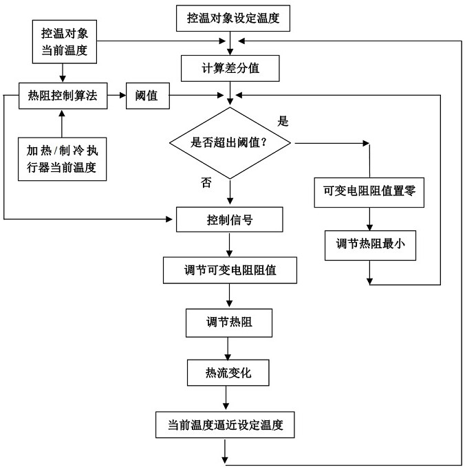
[0019] In order to achieve the purpose of the invention, based on the technical principle of variable thermal resistance of the semiconductor temperature difference module, the present invention provides a temperature control method based on passive variable thermal resistance, such as figure 2 Shown is a temperature control device 1 using semiconductor cooling / heating. The heating actuator and cooling actuator 2 of the temperature control device 1 are realized by a semiconductor cooling module, driven by a power supply 8, and the current direction of the power supply 8 is controlled by a controll...


PUM


Abstract

The invention provides a temperature control method based on passive variable thermal resistance. According to the technical scheme, a semiconductor temperature difference module for realizing the passive variable thermal resistance is arranged between a heating executor and a refrigeration executor of a temperature control device and a temperature control object; and according to an acquired temperature signal, the heat flow is changed by adjusting the thermal resistance, thereby realizing the temperature control. According to the temperature control method, the energy does not need to be consumed; no intermediate adjustment link exists; the response speed is increased; and the temperature control precision can be improved through the variable thermal resistance, for example, due to the two-way active temperature control matched with the semiconductor refrigeration, the heat balance can be rapidly achieved, and the high-precision temperature control is realized. The method is flexibleand convenient, is low in cost, effectively improves the temperature control precision, and can be widely applied to the high-precision temperature control in different temperature areas.

Description

technical field [0001] The invention relates to a temperature control method based on a passive variable thermal resistance, in particular to a temperature control method based on a semiconductor temperature difference module passive variable thermal resistance. Background technique [0002] Temperature is the most important controlled parameter, and high-precision temperature control has extremely wide application requirements and prospects. The temperature control system contains a pure hysteresis link, the heating / cooling actuator has a certain inertia, the inhomogeneity and thermal inertia of the controlled object, as well as the load change and external disturbance, which are easy to cause the system overshoot and oscillation and the change of the system parameters. This random and unpredictable change will undoubtedly increase the difficulty of realizing high-precision temperature control. [0003] Thermal Resistance (Thermal Resistance) reflects the comprehensive par...

Claims


Application Information

Patent Timeline
Patent Type & Authority Patents(China)
IPC IPC(8): G05D23/30
CPCG05D23/306
Inventor 郑艺华其他发明人请求不公开姓名
Owner QINGDAO UNIV
Learn More