
Upper limb rehabilitation training device with shoulder massage function
A training device and shoulder technology, applied in the field of medical appliances, can solve the problems of insignificant effect, inability of patients to recover quickly, and reduced effect, etc.
- Summary
- Abstract
- Description
- Claims
- Application Information
AI Technical Summary
Problems solved by technology
Method used
Image

Examples
Embodiment Construction
[0035] The following description serves to disclose the present invention to enable those skilled in the art to carry out the present invention. The embodiments in the following description are only examples, and those skilled in the art can think of other obvious modifications.
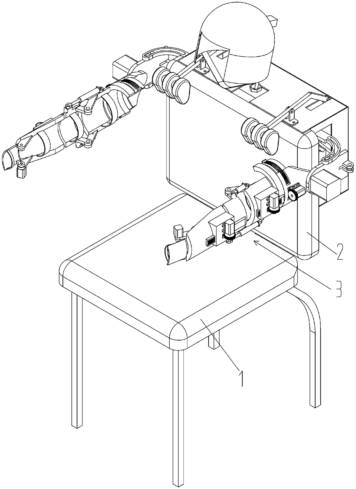
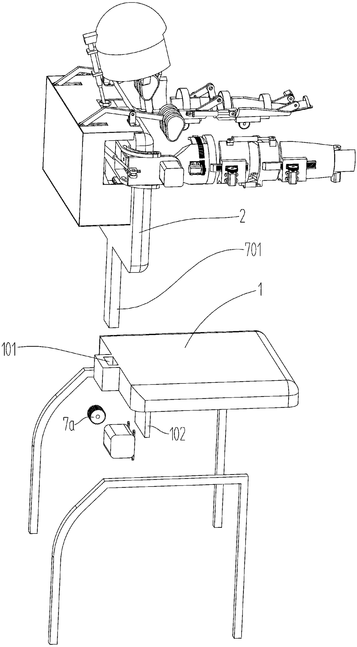
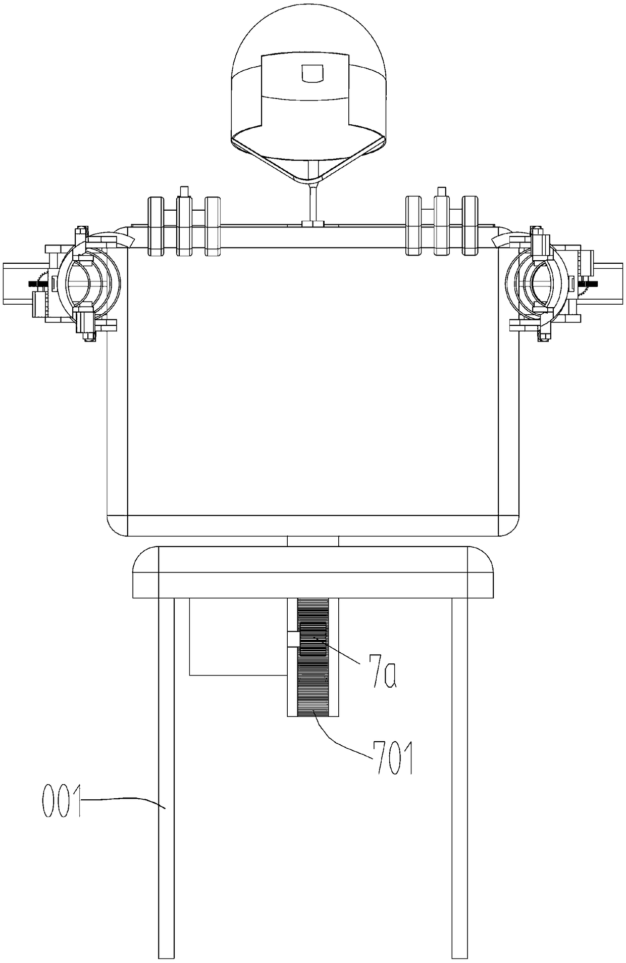
[0036] Such as Figure 1-15 As shown, a kind of upper limb rehabilitation trainer with shoulder massage function, comprises support leg 001, seat cushion 1, backrest 2, and described seat cushion 1 is installed on the upper end of support leg 001, and the rear side edge of described seat cushion 1 A non-circular insertion slot 101 is provided in the vertical direction, and the lower end of the backrest 2 is provided with a first rack 701 slidingly connected in the insertion slot 101; the lower surface of the seat cushion 1 The first drive motor 8a is installed by the support plate 102, and the first gear 7a engaged with the first rack 701 is installed on the output shaft of the first drive motor 8a;...
PUM
 Abstract
Description
Claims
Application Information