
Linear feeding device

A feeding device and linear technology, applied in the field of metal processing, can solve the problems of high material requirements, inability to straighten the material, and difficult to handle, and achieve the effect of simplifying the feeding mechanism, diversifying the selection of driving methods, and stabilizing the feeding.

Inactive Publication Date: 2019-01-11
ZHEJIANG NATE AUTOMOBILE STANDARD COMPONENT CO LTD
View PDF7 Cites 1 Cited by
  • Summary
  • Abstract
  • Description
  • Claims
  • Application Information

AI Technical Summary

Problems solved by technology

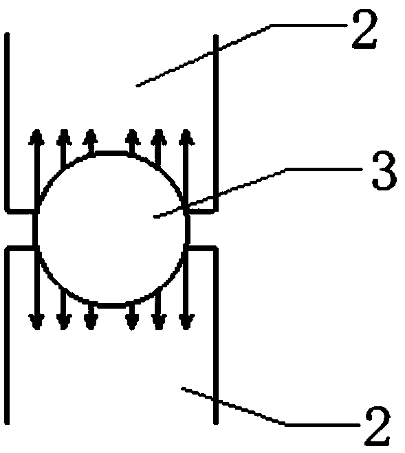
like figure 2 As shown, there is obviously a problem that the linear speed of each point where the groove contacts the wire is different (because the radius is different) which will cause: 1. The feed length is unstable and has a large deviation from the expected length; 2. Because The slippage will cause damage to the surface of the wire rod. The current solution is generally to use a stopper at the end of the wire rod to force the limit, but this method will cause damage to the end face and side of the wire rod, affect the product quality, and affect the production of short materials such as nuts. Can't use stopper
At present, the most advanced feeding method is straight-line feeding. The wire is clamped by a clamp and then fed through a connecting rod mechanism to realize linear motion feeding. Alignment of materials (in order to facilitate transportation and storage, various long-length materials are usually in a roll structure, and the clamp structure is difficult to handle such roll-shaped materials)

Method used


Image

  • Linear feeding device
  • Linear feeding device
  • Linear feeding device

Examples


Embodiment Construction

[0023] The present invention will be described in detail below in conjunction with specific embodiments. The following examples will help those skilled in the art to further understand the present invention, but do not limit the present invention in any form. It should be noted that those skilled in the art can make several changes and improvements without departing from the concept of the present invention. These all belong to the protection scope of the present invention.

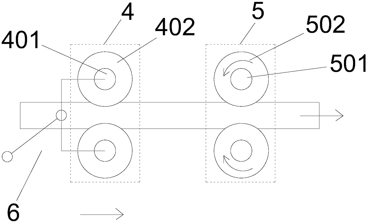
[0024] Such as image 3 As shown, a linear feeding device provided by the present invention includes: a moving wheel set 4, a fixed wheel set 5 and a driving part 6, and each roller 402 of the moving wheel set 4 is installed on the driving part 6 through a one-way bearing 401 respectively Each roller 502 of the fixed wheel set 5 is fixedly installed through a one-way bearing 501 respectively, and the driving part 6 drives the moving wheel set 4 to move back and forth in the feeding direction.

[0025] ...


PUM


Abstract

The invention provides a linear feeding device. The linear feeding device comprises a moving roller set, a fixed roller set and a driving part; each roller of the moving roller set is mounted on the driving part through one-way bearings; each roller of the fixed roller set is fixedly mounted through one-way bearings; the driving part drives the moving roller set to move back and forth in a feedingdirection; when the moving direction of the moving roller set is the same with the feeding direction, the one-way bearings of the moving roller set are in a locked state, and the one-way bearings ofthe fixed roller set are in a moving state; and when the moving direction of the moving roller set is opposite to the feeding direction, the one-way bearings of the moving roller set is in the movingstate, and the one-way bearings of the fixed roller set are in the locked state. The linear feeding device can realize precise control of the wire feeding length, and simplifies the structure of traditional feeding equipment.

Description

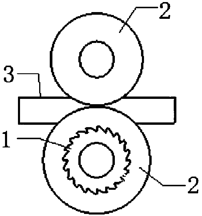
technical field [0001] The invention relates to the technical field of metal processing, in particular to a linear feeding device. Background technique [0002] Cold forming machine is a special process of cutting metal wires and performing cold heading and cold extrusion on the cut blanks to form parts. It is currently widely used in fastener production and has high efficiency and easy automatic production, because It is a cold forming without cutting process, so the accuracy of the feeding directly affects the quality of the product. [0003] Such as figure 1 As shown, the current cold forming machine generally uses the ratchet 1 to drive the roller 2 to feed the wire 3, but this feeding method is driven by the rotation of the roller, and the groove of the roller presses the wire to generate friction to push forward. Such as figure 2 As shown, there is obviously a problem that the linear speed of each point where the groove contacts the wire is different (because the r...

Claims


Application Information

Patent Timeline
Patent Type & Authority Applications(China)
IPC IPC(8): B21F23/00B21F11/00
Inventor 吴恒龙刘文斌
Owner ZHEJIANG NATE AUTOMOBILE STANDARD COMPONENT CO LTD
Learn More