A solder handle fixing steel ring

A technology for fixing steel rings and handles, which is applied in welding equipment, metal processing equipment, manufacturing tools, etc., can solve the problems of poor adjustability of fixed steel rings, decreased installation tightness, and unchanged maintenance, and achieves a significant fixing effect, The effect of stable installation and strong magnetic attraction ability

Active Publication Date: 2021-11-23
德盈科技(深圳)有限公司
View PDF14 Cites 0 Cited by
  • Summary
  • Abstract
  • Description
  • Claims
  • Application Information

AI Technical Summary

Problems solved by technology

[0004] The purpose of the present invention is to provide a soldering handle fixing steel ring to solve the problem that the existing soldering handle fixing steel ring proposed in the above background technology is generally fixed, and the installation method is single. When damage occurs, it is very easy to cause maintenance changes. At the same time, the adjustable performance of the existing solder handle fixed steel ring is poor, and it is generally installed by direct socketing. When vibration occurs during the processing, the steel ring is easily rotated, so that the tightness of the installation is reduced. question

Method used


Image

  • A solder handle fixing steel ring
  • A solder handle fixing steel ring
  • A solder handle fixing steel ring

Examples


Embodiment 1

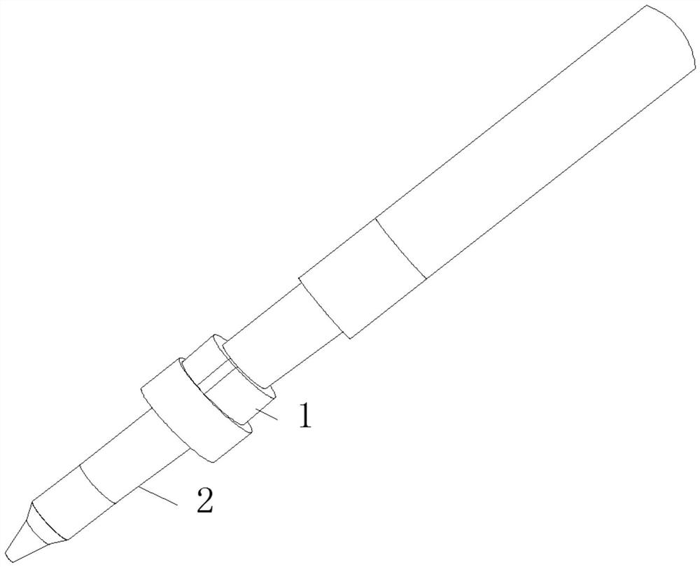
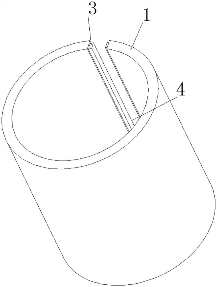
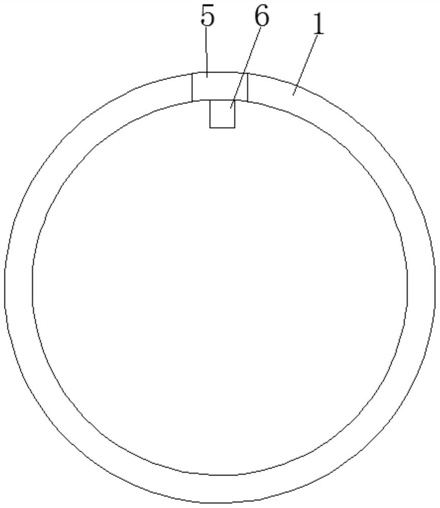
[0021] see Figure 1-4 , this embodiment provides a solder handle fixing steel ring, including a steel ring main body 1, a solder handle 2 is embedded in the middle of the steel ring main body 1, a cutout 4 is opened on one side of the steel ring main body 1, and the inside of the cutout 4 is embedded and installed There is a positioning block 5, the middle part of one side of the positioning block 5 is fixedly installed with a boss 6, and the two sides of the positioning block 5 close to the steel ring main body 1 are provided with mounting grooves 7, and the insides of the two mounting grooves 7 are slidingly connected with mounting platforms 3. The installation platform 3 is welded to the main body 1 of the steel ring.

[0022] In this embodiment, the steel ring main body 1 provides fixed support for the solder handle 2, and the setting of the cutout 4 facilitates the embedded installation of the positioning block 5, and a boss 6 is fixedly installed in the middle of one si...

Embodiment 2

[0024] see figure 1 , made further improvements on the basis of Example 1: the main body of the steel ring 1 is a stainless steel member, the stainless steel itself has good corrosion resistance, and the stainless steel can still maintain its excellent physical and mechanical properties at high temperatures, and its stability Excellent, fixed and tight, can be used for a long time, one end of the solder handle 2 is nested with a rubber ring, anti-slip protection, safe during installation, easy to install quickly, the inner diameter of the steel ring main body 1 is larger than the outer diameter of the solder handle 2 The size is convenient for quick assembly of the steel ring body 1 and the solder handle 2.


PUM


Abstract

The invention discloses a soldering handle fixing steel ring, which comprises a steel ring main body, a solder handle is embedded in the middle of the steel ring main body, a cutout is opened on one side of the steel ring main body, and a positioning device is embedded in the inside of the cutout. The middle part of one side of the positioning block is fixedly installed with a boss, the two sides of the positioning block close to the main body of the steel ring are provided with installation grooves, and the insides of the two installation grooves are slidingly connected with installation platforms. The installation table is welded with the main body of the steel ring. The present invention solves the problem that the existing solder handle fixed steel ring is generally fixed, and the installation method is single. When damage occurs, it is easy to cause the problem of unchanged maintenance. The adjustable performance of the steel ring is poor, and it is generally installed by direct socketing. When vibration occurs during processing, the steel ring is easily rotated, so that the tightness of the installation is reduced.

Description

technical field [0001] The invention relates to the technical field of soldering handles, in particular to a soldering handle fixing steel ring. Background technique [0002] In the process of electronic product processing, electronic components generally need to be soldered; as an automatic equipment, automatic soldering machines are gradually popularized and applied. Among them, for automatic soldering machines, the soldering gun is installed and fixed through the corresponding handle. . [0003] In the existing life, there are various solder gun mounting handle structures. However, for the existing solder gun mounting handles, there are generally defects of unreasonable design. The existing solder handle fixing steel rings are generally fixed The installation method is single, and when it is damaged, it is easy to cause the problem of constant maintenance. At the same time, the existing solder handle fixed steel ring has poor adjustability. Generally, it is installed by ...

Claims


Application Information

Patent Timeline
Patent Type & Authority Patents(China)
IPC IPC(8): B23K3/08
CPCB23K3/08
Inventor 黄育森李博
Owner 德盈科技(深圳)有限公司
Why Eureka
Try Eureka