Pump shaft grinding device

A grinding device and pump shaft technology, applied in the direction of grinding drive device, grinding/polishing safety device, grinding machine, etc., can solve the problem of reducing the convenience of grinding wheel and pump shaft, reducing the convenience of adding water to the water tank, and unable to adjust the telescopic column Length and other issues to achieve the effect of improving convenience, improving convenience, and avoiding slipping

Pending Publication Date: 2019-01-11
TUSON PRECISION MACHINE (JIAXING) CO LTD
View PDF0 Cites 2 Cited by
  • Summary
  • Abstract
  • Description
  • Claims
  • Application Information

AI Technical Summary

Problems solved by technology

[0002] At present, the existing pump shaft grinding devices still have some deficiencies. For example, the existing pump shaft grinding devices generally directly fit the pump shaft inside the splint, which may easily cause slippage during the rotation of the pump shaft. phenomenon, which reduces the stability of the pump shaft during the grinding process, and the length of the telescopic column cannot be adjusted according to the distance between the pump shaft and the grinding wheel, which reduces the convenience of adjusting the height of the grinding wheel and the pump shaft, and improves the operator's The labor intensity when using the grinding device, the existing pump shaft grinding device does not recycle the waste liquid, which increases the waste of water resources and reduces the convenience of adding water to the water tank

Method used

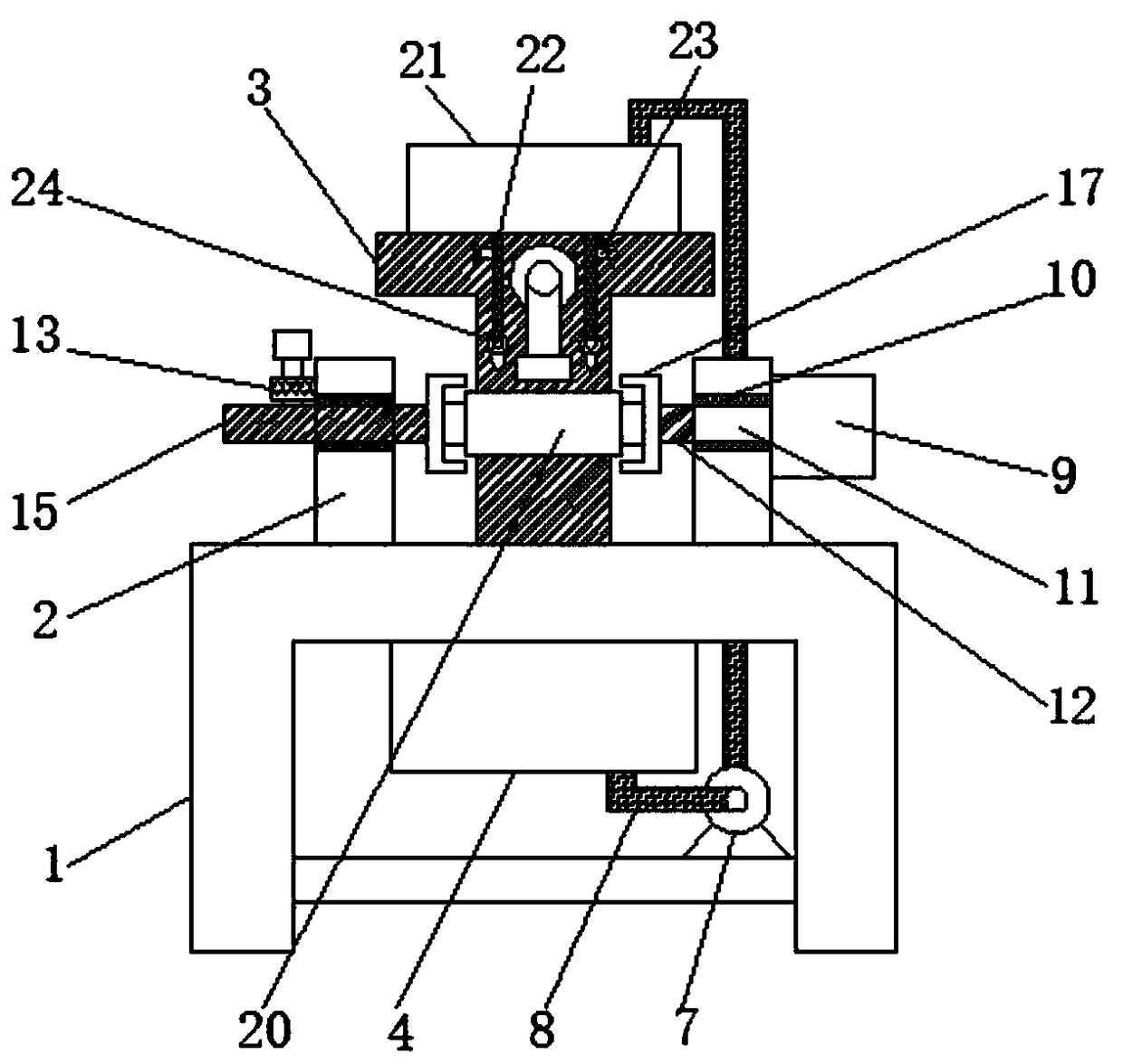
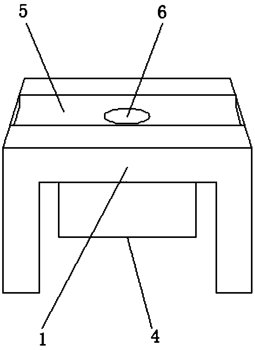
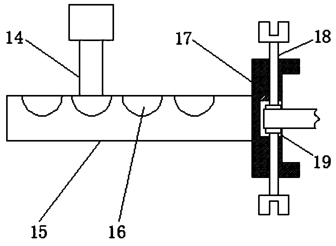

Image

  • Pump shaft grinding device
  • Pump shaft grinding device
  • Pump shaft grinding device

Examples


Embodiment Construction

[0024] The following will clearly and completely describe the technical solutions in the embodiments of the present invention with reference to the accompanying drawings in the embodiments of the present invention. Obviously, the described embodiments are only some, not all, embodiments of the present invention.

[0025] In describing the present invention, it should be understood that the terms "upper", "lower", "front", "rear", "left", "right", "top", "bottom", "inner", " The orientation or positional relationship indicated by "outside", etc. is based on the orientation or positional relationship shown in the drawings, and is only for the convenience of describing the present invention and simplifying the description, rather than indicating or implying that the referred device or element must have a specific orientation, so as to Specific orientation configurations and operations, therefore, are not to be construed as limitations on the invention.

[0026] see Figure 1-4 ,...


PUM


Abstract

The invention discloses a pump shaft grinding device. The pump shaft grinding device structurally comprises a support frame. The support frame is provided with fixing plates, a support pillar, a wasteliquid collection and filter tank, a waste liquid tank, a leakage hole and a circulating pump. The fixing plates are fixedly connected to the left side and the right side of the upper surface of thesupport frame. The fixing pillar is fixedly connected to the position behind the upper surface of the support frame. The waste liquid collection and filter tank is fixedly connected to the bottom of the support frame. The waste liquid tank is located in the middle of the upper surface of the support frame. The leakage hole is formed in the middle of the waste liquid tank. The circulating pump is fixedly connected to the right side below the support frame. By means of the pump shaft grinding device, the application scope of the grinding device is expanded, the phenomenon that a pump shaft slipsin the rotating process is avoided, and stability, achieved in the grinding process, of the pump shaft is improved; a coupling is combined with an extending-and-contracting pillar, and the length ofthe extending-and-contracting pillar can be adjusted according to the distance between the pump shaft and a grinding wheel; and labor intensity formed when an operator uses the grinding device is lowered.

Description

technical field [0001] The invention relates to the technical field of grinding devices, in particular to a pump shaft grinding device. Background technique [0002] At present, the existing pump shaft grinding devices still have some deficiencies. For example, the existing pump shaft grinding devices generally directly fit the pump shaft inside the splint, which may easily cause slippage during the rotation of the pump shaft. phenomenon, which reduces the stability of the pump shaft during the grinding process, and the length of the telescopic column cannot be adjusted according to the distance between the pump shaft and the grinding wheel, which reduces the convenience of adjusting the height of the grinding wheel and the pump shaft, and improves the operator's The labor intensity when using the grinding device, the existing pump shaft grinding device does not recycle the waste liquid, which increases the waste of water resources and reduces the convenience of adding water...

Claims


Application Information

Patent Timeline
Patent Type & Authority Applications(China)
IPC IPC(8): B24B27/00B24B5/04B24B55/06B24B47/12C02F1/00
CPCB24B27/0015B24B5/045B24B47/12B24B55/06C02F1/001
Inventor 杨正山黄祖标
Owner TUSON PRECISION MACHINE (JIAXING) CO LTD
Why Eureka
Try Eureka