Mechanical jaw

A mechanical claw and clamping claw technology, applied in the field of cooking equipment, can solve the problems of easy falling of the barrel and unstable operation of the equipment, and achieve the effect of avoiding the in-place grasping, simple structure and strong load capacity.

Active Publication Date: 2019-01-11
四川长虹智能制造技术有限公司
View PDF5 Cites 6 Cited by
  • Summary
  • Abstract
  • Description
  • Claims
  • Application Information

AI Technical Summary

Problems solved by technology

[0004] Therefore, in order to solve the problems that the barrel is easy to fall and the equipment is unstable during the material transportation, a mechanical claw is provided.

Method used


Image

  • Mechanical jaw
  • Mechanical jaw
  • Mechanical jaw

Examples


Embodiment Construction

[0026] The technical solutions of the present invention will be clearly and completely described below in conjunction with the accompanying drawings. Apparently, the described embodiments are some of the embodiments of the present invention, but not all of them. Based on the embodiments of the present invention, all other embodiments obtained by persons of ordinary skill in the art without making creative efforts belong to the protection scope of the present invention.

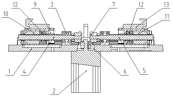
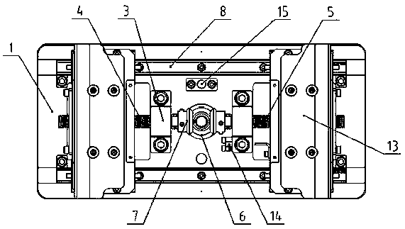
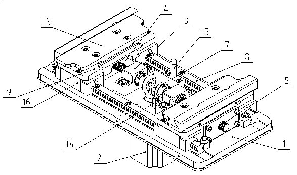
[0027] Figure 1 to Figure 4 A mechanical claw provided by the present invention is shown.

[0028] Such as figure 1 As shown, a mechanical claw of the present invention includes: a jaw substrate 1, a drive motor 2, two screw fixing seats 3, a first screw 4, a second screw 5, a driving bevel gear 6, and a driven umbrella The gear 7; the driving motor 2 is fixedly installed on the lower part of the jaw base plate 1; the driving motor 2 shaft end is provided with an active bevel gear 6, and the active bevel ge...


PUM


Abstract

The invention discloses a mechanical jaw. The mechanical jaw comprises a clamping jaw substrate, a driving motor, two lead screw fixed bases, a first lead screw, a second lead screw, a driving bevel gear and driven bevel gears; the driving motor is fixedly mounted at the lower part of the clamping jaw substrate; the driving bevel gear is arranged at the shaft end of the driving motor, and is positioned in the center position of the clamping jaw substrate; the lead screw fixed bases are fixedly mounted at the upper part of the clamping jaw substrate, and are distributed on two sides of the driving bevel gear in the length direction of the clamping jaw substrate; the first lead screw and the second lead screw are fixedly mounted on the two lead screw fixed bases; the driven bevel gears are arranged at the inner side shaft ends of the first lead screw and the second lead screw; and when the driving motor drives the driving bevel gear to rotate, the driving bevel gear drives the driven bevel gears to rotate in different directions. The mechanical jaw firmly clamps a charging barrel in the material conveying process to achieve stable equipment operation.

Description

technical field [0001] The invention relates to the technical field of cooking equipment, in particular to a mechanical claw. Background technique [0002] A cooking machine is a kind of kitchen cooking utensil that can realize automatic feeding and stir-frying. For a cooking machine, it is generally necessary to set up multiple material boxes, and the feeding mechanism will pour the dishes into the wok according to the preset program, which requires feeding The mechanism reaches the predetermined position within the predetermined time, clamps the material box, and after the dishes in the material box are poured into the wok, returns the material box to the initial position, and releases the material box. [0003] At present, clamps and travel switches are mostly used in cooking machines to realize the actions of clamping, opening and returning the material box to the material. Since the holding of the material box by the clamp is completed by the clamp connecting rod, it is...

Claims


Application Information

Patent Timeline
Patent Type & Authority Applications(China)
IPC IPC(8): B25J15/02B25J15/08
CPCB25J15/0213B25J15/08B25J15/083
Inventor 王金龙潘晓勇王川濮
Owner 四川长虹智能制造技术有限公司
Why Eureka
Try Eureka