Sealing device and vacuum tire mould

A sealing device and tire mold technology, applied in tires, household appliances, other household appliances, etc., can solve problems such as rupture of sealing rings, avoid excessive extrusion and impact, increase production efficiency, and ensure the effect of production efficiency

Active Publication Date: 2019-01-11
HIMILE MECHANICAL SCI & TECH (SHANDONG) CO LTD
View PDF7 Cites 6 Cited by
  • Summary
  • Abstract
  • Description
  • Claims
  • Application Information

AI Technical Summary

Problems solved by technology

[0004] In the tire production process, in order to improve the appearance quality of the tire, ensure that there is no lack of rubber on the surface, or avoid the production of some raw rubber, vacuum molds are often used in the vulcanization process, especially in passenger tires, which are widely used; the existing vacuum molds, Due to the limitations of the structure, the sealing ring between the guide ring and the base is often broken, and the sealing ring needs to be replaced frequently

Method used


Image

  • Sealing device and vacuum tire mould
  • Sealing device and vacuum tire mould
  • Sealing device and vacuum tire mould

Examples


Embodiment 1

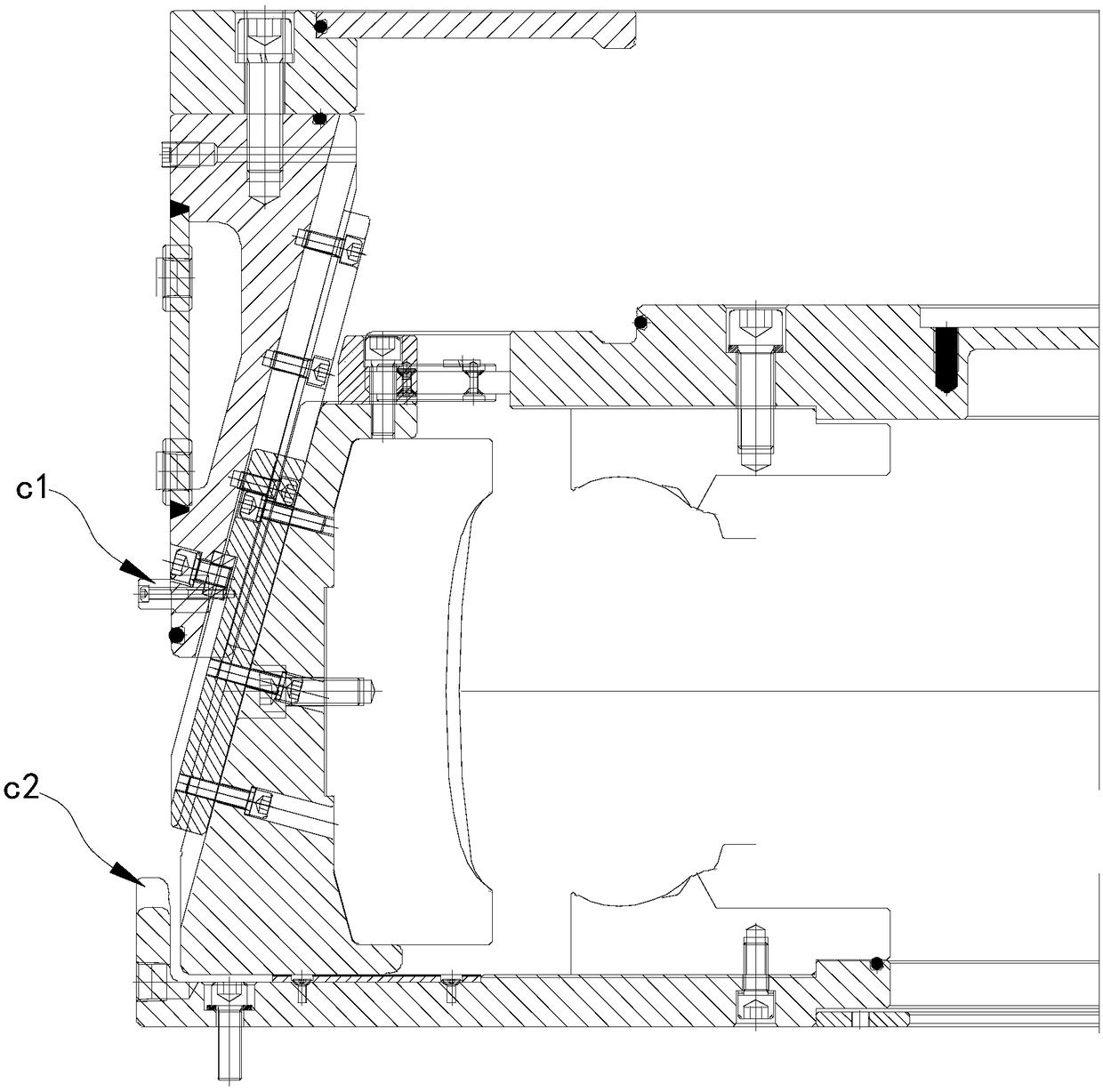
[0057] Please refer to Figure 4 to Figure 7 , a sealing device 10, which cooperates with the guide ring 21 and the base 22 of the vacuumized tire mold 20 to seal the vacuumized tire mold 20, including a first sealing member 100, a floating sealing ring 200 and an elastic device 300.

[0058] The base 22 has a circumferentially arranged first annular groove 22a; the floating seal ring 200 is disposed in the first annular groove 22a through an elastic device 300; the elastic device 300 is configured to provide an elastic force that makes the floating seal ring 200 approach the guide ring 21; The first sealing member 100 is embedded in the end of the floating sealing ring 200 close to the guide ring 21 , and the first sealing member 100 is configured to cooperate with the guide ring 21 and the sealing device 10 to achieve a sealing effect.

[0059] The sealing device 10 cooperates with the guide ring 21 and the base 22 of the vacuum tire mold 20. The sealing method of the guide ...

Embodiment 2

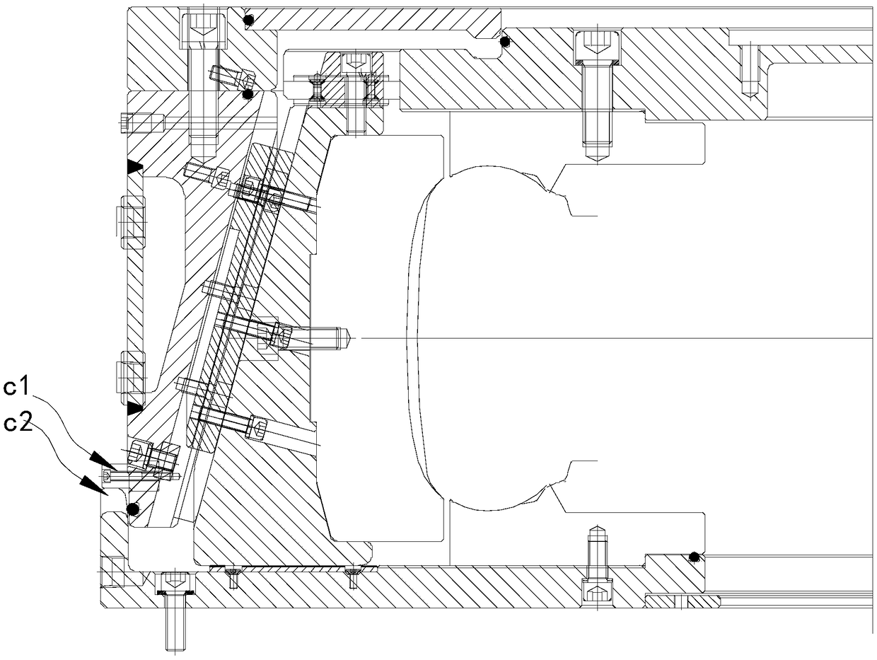
[0089] Figure 6 A schematic diagram of a sealing device 10 is provided for Embodiment 2 of the present invention. Please refer to Figure 6 , it can be seen from the figure that the sealing device 10 in this embodiment is roughly the same, the difference is that the sealing device 10 in this embodiment includes sealing structures in other positions, such as between the upper cover 24 and the guide ring 21 The sealing structure between the slider 25 and the base 22, the sealing structure at other positions and the sealing device between the base 22 and the guide ring 21 are combined to provide a seal for the vacuuming operation and support the vacuuming operation. .

[0090] This embodiment also provides a vacuumized tire mold 20, which includes any one of the sealing devices 10 described above. Vacuum tire mold 20 comprises loam cake 24, guide ring 21, slide block 25, pattern block, vacuum air nozzle 26, and vacuum air nozzle 26 can be arranged on guide ring 21 top, also c...

Embodiment 3

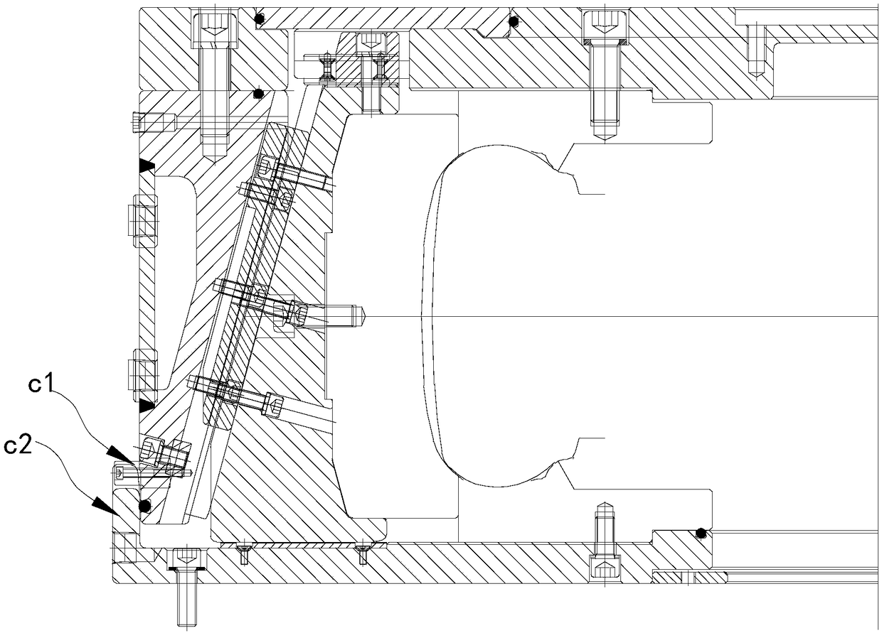
[0092] This embodiment of the present invention also provides a vacuumized tire mold 20, which includes any one of the sealing devices 10 described above. Since the vacuum tire mold 20 is equipped with the above-mentioned sealing device 10, it can also avoid excessive extrusion and impact of the sealing ring, thereby protecting the sealing ring, prolonging the service life of the sealing ring, and ensuring production efficiency.

[0093] At the same time, the vacuumized tire mold 20 provided by the embodiment of the present invention can be obtained through simple modification on the basis of the existing non-vacuumized vacuumized tire mold, and the vacuuming operation can be performed in advance, which saves costs and increases production efficiency.

[0094] In the present embodiment, the specific implementation of the vacuum tire mold 20 is provided, please refer to Figure 4-Figure 6 . Wherein, a kind of usage mode of vacuumizing tire mold 20 is as follows:

[0095] refe...


PUM


Abstract

The present invention provides a sealing device and a vacuum tire mould. The sealing device matches a guide ring and a base of the vacuum tire mould to seal the vacuum tire mould. The sealing device includes a first sealing element, a floating sealing ring and an elastic device. The base has a first circular groove disposed in the circumferential direction. The floating sealing ring is disposed inthe first circular groove through the elastic device. The elastic device is configured to provide an elastic force to enable the floating sealing ring to approach the guide ring. The first sealing element is embedded in the end of the floating sealing ring close to the guide ring. The first sealing element is configured to match the guide ring and the sealing device to realize a sealing effect.

Description

technical field [0001] The invention relates to the field of tire vacuum molds, in particular to a sealing device and a vacuum tire mold. Background technique [0002] figure 1 It is a structural schematic diagram of a vacuum tire mold in the prior art, figure 2 It is a structural schematic diagram of a vacuumized tire mold in the prior art about to be sealed, image 3 It is a structural schematic diagram of the closed state of the vacuumized tire mold in the prior art. From figure 1 It can be seen from the figure that the existing vacuum tire mold includes a guide ring 21, a base 22, an upper cover 24, a slider 25, a vacuum nozzle 26, a central mechanism 27b, a capsule 29, a blank 30, a positioning pin c1, a positioning pin notch. The base 22 is circular, and the peripheral edge of the base 22 is provided with positioning notches. The part of the peripheral edge of the guide ring 21 close to the base is equipped with a positioning pin c1, and the positioning pin c1 c...

Claims


Application Information

Patent Timeline
Patent Type & Authority Applications(China)
IPC IPC(8): B29C33/00B29L30/00
CPCB29C33/0038B29L2030/00
Inventor 管贻敏许彦霞杜平张伟单既强齐世伟陈忠磊沈锡良刘志兰
Owner HIMILE MECHANICAL SCI & TECH (SHANDONG) CO LTD
Why Eureka
Try Eureka