
Pulling piece and material skeleton breakage and separation device

A separation device and pull-tab technology, which is applied in the field of injection molding products and bone breaking separation devices, can solve the problems of product appearance not as good as manual trimming, high mold cost, low output, etc., so as to save manual sorting and collection processes, The separation quality is guaranteed and the reset situation is stable.

Active Publication Date: 2019-01-11
FUJIAN SBS ZIPPER SCI & TECH CO LTD
View PDF5 Cites 1 Cited by
  • Summary
  • Abstract
  • Description
  • Claims
  • Application Information

AI Technical Summary

Problems solved by technology

[0002] Traditional injection molding products have a common feature, that is, the product after demoulding together with the head, and then separated by manual trimming, the disadvantage is that it is labor-intensive and time-consuming, and the efficiency is low. The cost of the mold is high, and it is generally suitable for large-scale production and perennial production. It is not suitable for injection molding products with low output and multi-point gates, and the appearance of the separated products is not as good as that of manual trimming.

Method used


Image

  • Pulling piece and material skeleton breakage and separation device
  • Pulling piece and material skeleton breakage and separation device
  • Pulling piece and material skeleton breakage and separation device

Examples


Embodiment Construction

[0068] The following will clearly and completely describe the technical solutions in the embodiments of the present invention with reference to the drawings in the embodiments of the present invention. Obviously, the described embodiments are preferred embodiments of the invention and should not be seen as excluding other embodiments. Based on the embodiments of the present invention, all other embodiments obtained by persons of ordinary skill in the art without creative efforts fall within the protection scope of the present invention.

[0069] In the claims, description and above-mentioned drawings of the present invention, unless otherwise clearly defined, the terms "first", "second" or "third" are used to distinguish different objects, not for Describe a specific order.

[0070] In the claims, specification and above-mentioned drawings of the present invention, unless otherwise clearly defined, for orientation words, such as using the terms "center", "transverse", "longit...


PUM


Abstract

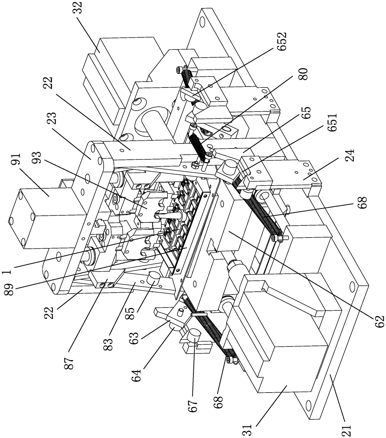
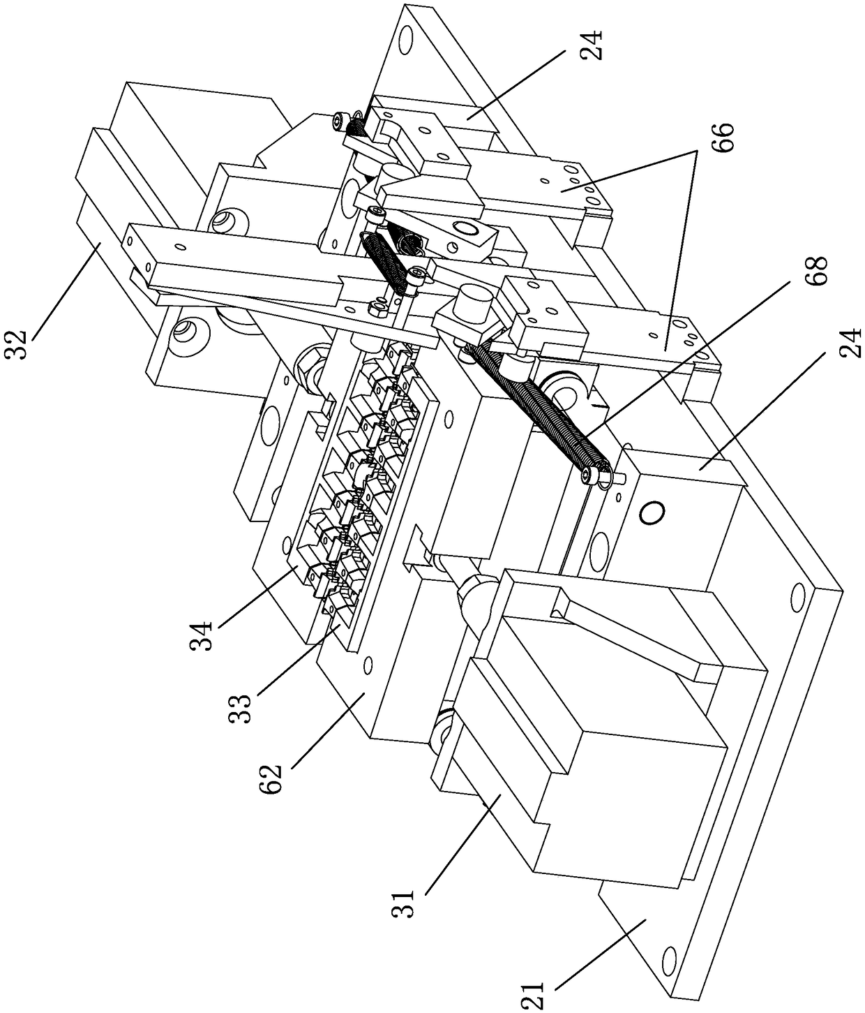
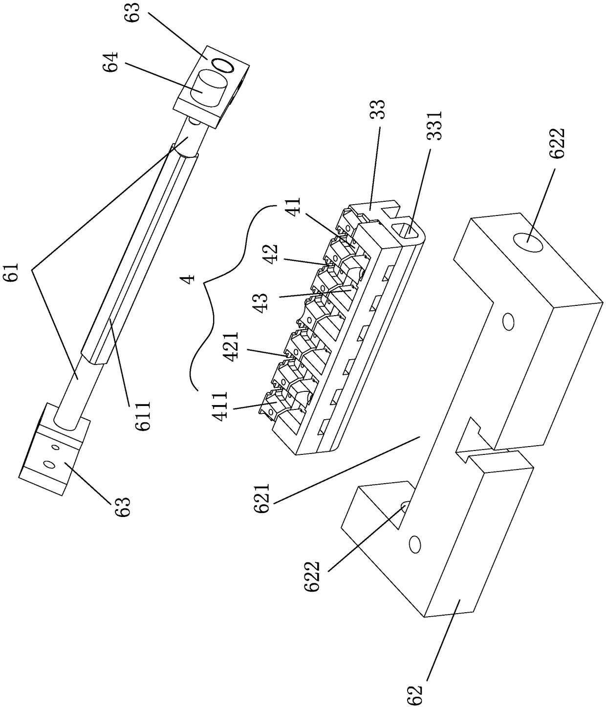
The invention discloses a pulling piece and material skeleton breakage and separation device. The pulling piece and material skeleton breakage and separation device is used for separating pulling pieces from an injection molded part. The injection molded part comprises a material skeleton and the pulling pieces connected and distributed on the two sides of the material skeleton through material stems. The pulling piece and material skeleton breakage and separation device comprises a rack, a first limiting groove, a second limiting groove, a breakage and separation mechanism and a hold-down mechanism, wherein the breakage and separation mechanism and the hold-down mechanism are arranged on the rack; the first limiting groove and the second limiting groove are used for embedment of the pulling pieces and the material stems connected with the pulling pieces; the breakage and separation mechanism is used for separating the first limiting groove and the second limiting groove in the direction perpendicular to the material skeleton; the hold-down mechanism is used for pressing the material skeleton when the first limiting groove and the second limiting groove are separated to enable thematerial skeleton not to move relative to the rack. The breakage and separation mechanism is further provided with a shift-in mechanism and a rotary discharge mechanism, so that the injection molded part falls into the breakage and separation mechanism from the shift-in mechanism and then is automatically discharged after the material skeleton is broken, separated and turned over. Through the scheme, the separation efficiency of the pulling piece and material skeleton breakage and separation device is higher than manual trimming, and the separation quality is higher than manual operation.

Description

technical field [0001] The invention relates to a device for breaking and separating an injection molded product and a material bone, in particular to a device for breaking and separating a pull piece and a material bone. Background technique [0002] Traditional injection molding products have a common feature, that is, the product after demoulding together with the head, and then separated by manual trimming, the disadvantage is that it is labor-intensive and time-consuming, and the efficiency is low. The cost of the mold is high, and it is generally suitable for large-scale production and perennial production. It is not suitable for injection molding products with low output and multi-point gates, and the appearance of the separated products is not as good as manual trimming. Contents of the invention [0003] The purpose of the present invention is to overcome the above-mentioned defects or problems in the background technology, and provide a breaking and separating de...

Claims


Application Information

Patent Timeline
Patent Type & Authority Applications(China)
IPC IPC(8): B29C45/38
CPCB29C45/382B29C2793/0027B29C2793/009
Inventor 魏开铧张田朱松峰张国民
Owner FUJIAN SBS ZIPPER SCI & TECH CO LTD
Learn More