
Wheel inner tube and preparation method thereof
A technology for inner tubes and wheels, applied in tire measurement, tire parts, vehicle parts, etc., can solve problems such as drivers unable to find and tire inner tubes leaking.
- Summary
- Abstract
- Description
- Claims
- Application Information
AI Technical Summary
Problems solved by technology
Method used
Image

Examples
Embodiment Construction
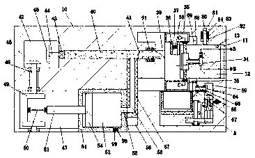
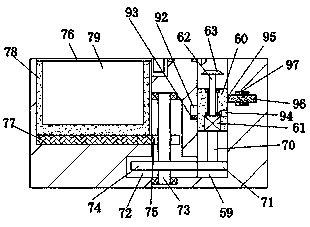
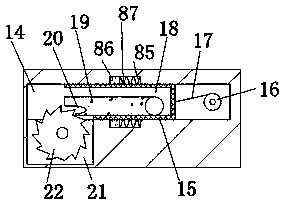
[0019] Combine below Figure 1-4 The present invention will be described in detail.
[0020] refer to Figure 1-4 , according to an embodiment of the present invention a tire inner tire and its preparation method, the device used in this method includes a device body 10, a fixing device arranged in the device body 10, an inflation device arranged in the device body 10 And the detection device arranged in the device main body 10, the fixing device includes a first cavity 11 arranged in the device main body 10, a left and right sliding and rotatable setting in the first cavity 11 There is a first working block 12, the upper end surface of the first working block 12 is provided with a first card hole 13 with an opening upward, and a second cavity 14 is arranged in the first working block 12, and the second cavity 14 is provided with a second work block 15 that can slide back and forth, and the rear end of the second work block 15 is rotatably provided with a first reel 16, and ...
PUM
 Abstract
Description
Claims
Application Information