A winch rope arrangement

A technology of rope arranging devices and winches, which is applied in hoisting devices and clockwork mechanisms, etc., can solve the problems of short service life of ropes and narrow application range of rope arranging devices, so as to improve service life, increase application range, and move flexibly Effect

Active Publication Date: 2019-11-08
WUHAN MARINE MACHINERY PLANT
View PDF12 Cites 0 Cited by
  • Summary
  • Abstract
  • Description
  • Claims
  • Application Information

AI Technical Summary

Problems solved by technology

[0003] The purpose of the present invention is to overcome the defects and problems of the narrow application range and short service life of the rope guide in the prior art, and provide a winch rope guide with a wide application range and a long service life of the rope

Method used


Image

  • A winch rope arrangement
  • A winch rope arrangement
  • A winch rope arrangement

Examples


Embodiment 1

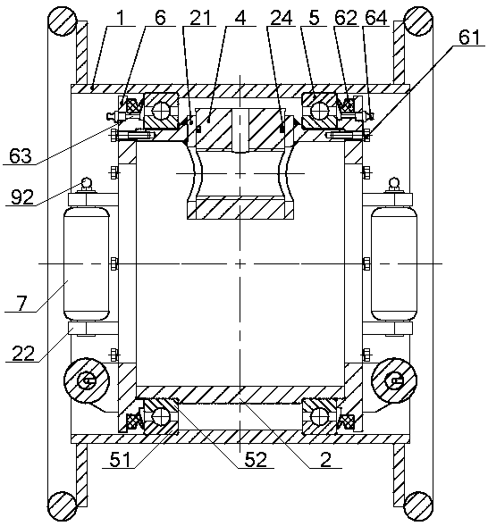
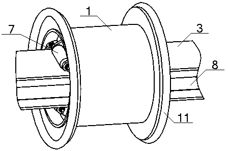
[0043] see Figure 1 to Figure 3 , a winch rope-removing device, comprising a rope-removing device cylinder 1 and a rope-removing device seat 2, the rope-removing device seat 2 is a cylindrical tubular structure, and the interior of the rope-removing device seat 2 runs through a slide along its axis direction. Rail 3, installation sleeve 21 is arranged on the outer peripheral surface of the rope row device seat 2, and the screw nut 4 is arranged in the installation sleeve 21, and the outer peripheral surface of the rope row device seat 2 is set on the rope row device cylinder 1 through the bearing 5 On the inner circumferential surface of the rope guide seat 2, both ends of the rope guide seat 2 are provided with a rope guide end cover 6, and the two ends of the rope guide seat 2 are provided with three rollers 7, and the three rollers 7 are connected to the slide rail 3 respectively. The three end surfaces of the sliding rail 3 are in contact with each other, and the other en...

Embodiment 2

[0045] Basic content is the same as embodiment 1, the difference is:

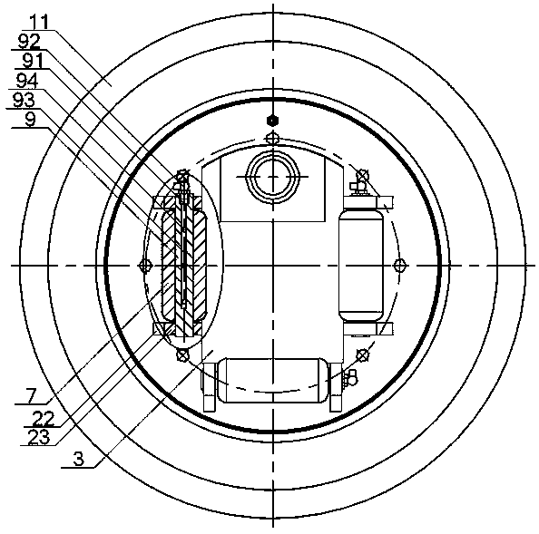
[0046] see Figure 1 to Figure 3 , the roller 7 is a cylindrical structure, the roller 7 is set on the roller shaft 9, and the roller 7 and the roller shaft 9 are in clearance fit, and the two ends of the roller shaft 9 are respectively installed on the two ear plates 22 on the rope row seat 2 Above, a retaining ring 23 is provided between the end of the roller shaft 9 and the ear plate 22; the end of the roller shaft 9 is provided with a No. 1 oil injection hole 91, and a No. 1 oil nozzle 92 is installed in the No. 1 oil injection hole 91. The roller The shaft 9 is provided with an oil groove 93 communicating with the No. 1 oil hole 91 along its axial direction, and the outer circumferential surface of the roller shaft 9 is provided with an oil hole 94 communicating with the oil groove 93; the manufacturing materials of the roller 7 and the roller shaft 9 All are stainless steel.

Embodiment 3

[0048] Basic content is the same as embodiment 1, the difference is:

[0049] see figure 1 , the number of the bearings 5 ​​is two, and the two bearings 5 ​​are symmetrically arranged at both ends of the rope rower seat 2; the inner peripheral surface of the rope rower cylinder 1 is provided with a No. Cooperate with the outer ring 51 of the bearing 5, the outer peripheral surface of the said rope row device seat 2 is provided with a No. 6 to block the bearing 5; the end cover 6 of the rope arrangement is fixedly installed on the seat 2 of the rope arrangement through bolts 61 and spring washers, the end cover 6 of the rope arrangement blocks the inner ring 52 of the bearing 5, and the end cover 6 of the rope arrangement A V-shaped ring 62 is installed, and the lip of the V-shaped ring 62 is in contact with the outer ring 51 of the bearing 5; the end cover 6 of the rope arranger is provided with a second oil injection hole 63, and two oil injection holes 63 are installed in t...


PUM


Abstract

The invention discloses a winch rope guider. The winch rope guider comprises a rope guider barrel and a rope guider base. Retaining flanges are arranged at the two ends of the rope guider barrel correspondingly. The rope guider base is of a cylinder-shaped tubular structure. A slide rail penetrates through the interior of the rope guider base in the axis direction of the rope guider base. A mounting sleeve is arranged on the outer circumferential surface of the rope guider base. A lead screw nut is arranged in the mounting sleeve. The outer circumferential surface of the rope guider base is sleeved with the inner circumferential surface of the rope guider barrel through bearings. Rope guider end covers are arranged at the two ends of the rope guider base correspondingly. Three rollers arearranged on each of the two ends of the rope guider base and make contact with three end surfaces of the slide rail correspondingly. A lead screw matched with the lead screw nut is arranged on the other end surface of the slide rail. By means of the winch rope guider according to the design, the application range of the rope guider is expanded, the service life of a rope is prolonged, and the ropeguiding effect is improved.

Description

technical field [0001] The invention relates to the technical field of winches, in particular to a winch rope arranger, which is mainly suitable for improving the application range of the rope arranger and improving the service life of ropes. Background technique [0002] The wire rope winding of anchor winch, mooring winch of wire rope, etc. should be regular and neat, and no cross winding is allowed, otherwise the wire rope under load cannot be released normally. Steel wire ropes are generally wound in multiple layers, so a rope puller is generally required. The rope pullers of these winches can withstand the directional load of the wire rope to a certain extent, and the guide of the cable pullers is a fully enclosed structure. For the hose winch and large cable winch on the FPSO, the working conditions are different from the above winches. During the process of taking up the pipe or cable, there is no external load on the free end of the hose or cable, and the rope pulle...

Claims


Application Information

Patent Timeline
Patent Type & Authority Patents(China)
IPC IPC(8): B66D1/38
CPCB66D1/38
Inventor 周英辉熊大柱甘正林王坚白俊江
Owner WUHAN MARINE MACHINERY PLANT
Why Eureka
Try Eureka