Underground drainage pipeline repair system and repair method

A technology for underground drainage and repairing systems, which can be applied to sewer pipeline systems, waterway systems, water supply devices, etc.

Inactive Publication Date: 2019-01-11
张桂华
View PDF5 Cites 6 Cited by
  • Summary
  • Abstract
  • Description
  • Claims
  • Application Information

AI Technical Summary

Problems solved by technology

Although this method adopts the principle of non-excavation, there are still many shortcomings. For example, after

Method used


Image

  • Underground drainage pipeline repair system and repair method
  • Underground drainage pipeline repair system and repair method
  • Underground drainage pipeline repair system and repair method

Examples


Embodiment 1

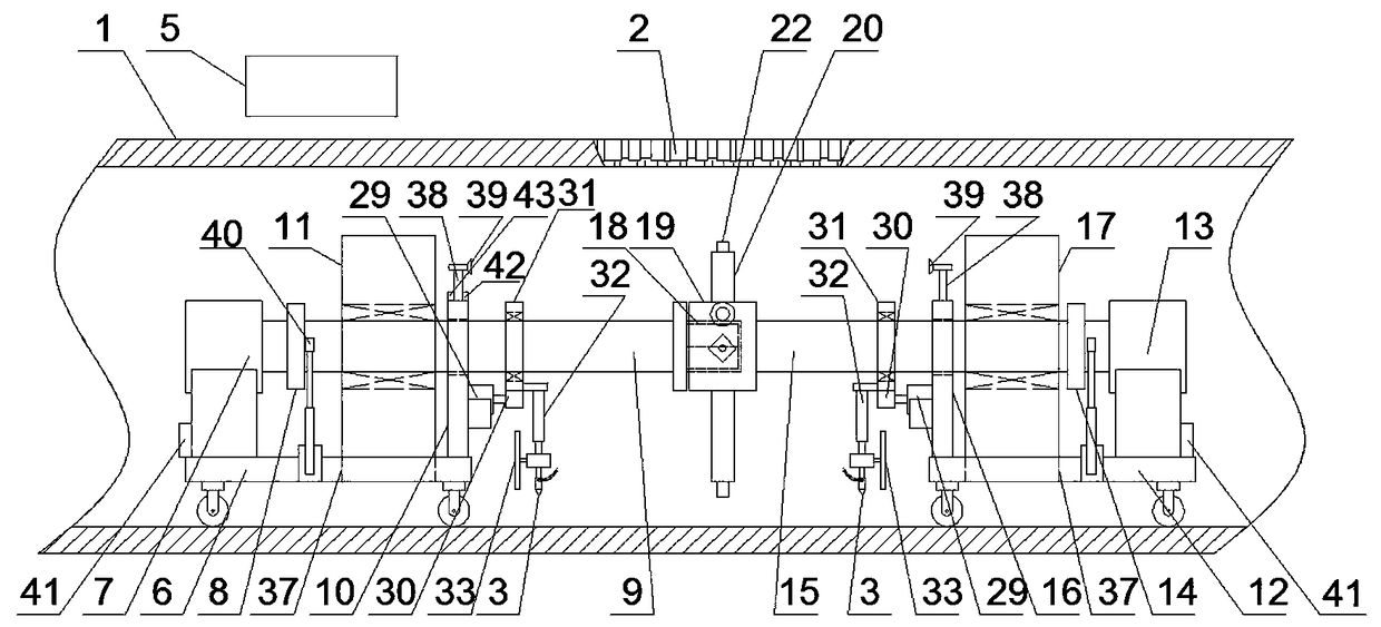
[0049] An underground drainage pipeline repair system and repair method, including a first working mechanism located on one side of the internal collapse and deformation of the drainage pipeline 1 to be repaired, and a second working mechanism located on the other side of the internal collapse and deformation of the drainage pipeline 1 to be repaired. Mechanism, the third working mechanism arranged between the first working mechanism and the second working mechanism, which is arranged on the first working mechanism and the second working mechanism for guiding and positioning the working process and monitoring the construction status The monitoring mechanism is respectively arranged on the right side of the first working mechanism and the left side of the second working mechanism. The cutting mechanism for circularly cutting the drainage pipe is arranged on the first quick-drying cement nozzle 3 on the cutting mechanism. An auxiliary stable mechanism 40 for smooth travel on the ...

Embodiment 2

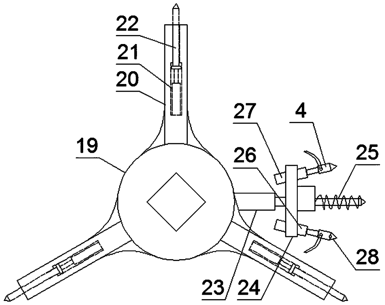
[0065] The difference from Embodiment 1 is that the third working mechanism includes three cylinders 20 with constricted openings arranged radially on the outer surface of the inner polygonal sleeve 19, and all the cylinders 20 are uniform in circumference. Distributed on the outer surface of the inner polygonal sleeve 19, a first automatic telescopic rod 21 is arranged in the axial direction in the cylinder body 20, and an insertion rod 22 is arranged at the end of the first automatic telescopic rod 21, and the insertion rod 22 The end portion protrudes from the constriction opening of the cylinder body 20 .

[0066] The third working mechanism also includes a second automatic telescopic rod 23 arranged radially on the outer surface of the inner polygonal sleeve 19, the end of the second automatic telescopic rod 23 is provided with a bearing plate 24, and the bearing plate 24, a drill bit 25, a third automatic telescopic rod 26 and a sixth automatic telescopic rod 27 are arra...

Embodiment 3

[0071] The difference between it and the second embodiment is that the cutting mechanism includes a low-speed motor 29 arranged on the side of the corresponding shaft seat, a driving gear 30 arranged on the output shaft of the low-speed motor 29, and a drive gear 30 arranged on the corresponding rotating shaft through a bearing sleeve and The driven gear 31 matched with the driving gear 30, the fourth automatic telescopic rod 32 arranged on the end face of the driven gear 31, and the end of the fourth automatic telescopic rod 32 are used to divide the parts to be repaired. The concrete cutting machine 33 of drainage pipeline 1, described first quick-drying cement nozzle 3 is arranged on the shell bottom of described concrete cutting machine 33; The structure of the cutting mechanism is the same, the difference is that: the low-speed motor on the first working mechanism is set on the right side of the first shaft seat, and its driven gear is sleeved on the first rotating shaft t...


PUM


Abstract

The invention discloses an underground drainage pipeline repair system and repair method. The underground drainage pipeline repair system includes a first working mechanism on one side of an internalcollapse deformation of a drainage pipe to be repaired, a second working mechanism located on the other side, a third working body disposed between the first working body and the second working body,a monitoring mechanism and an auxiliary stabilizing mechanism arranged on the first working mechanism and the second working mechanism, a cutting mechanism respectively arranged on the right side of the first working mechanism and the left side of the second working mechanism, a quick-drying cement nozzle arranged on the cutting mechanism and the third working mechanism, and control mechanisms, the invention only needs to separate and cut the collapse deformation part of the drainage pipe, Then it is rotated to the side or bottom, and finally, the first dry cement nozzle and the second quick-drying cement nozzle are used for cement filling and repairing the cutting seam, the socket hole and the collapse deformation part, so that no new pipeline is needed for repairing, and the collapse part can be smoothly accessed in the complicated sewage pipe at the same time.

Description

technical field [0001] The invention relates to the technical field of municipal sewage pipeline repair, in particular to an underground drainage pipeline repair system and a repair method. Background technique [0002] Urban drainage pipes are one of the important infrastructures that support social development and ensure people's lives. Pipeline maintenance is a necessary means to ensure its normal mechanism and function. Pipeline repair work is mainly carried out through two repair methods: excavation repair and trenchless repair. Among them, the excavation repair is to directly dig the pipeline, and then repair the pipeline to be repaired. The environmental problems and economic impact of the excavation and repair of the pipeline are relatively large, and it is easy to cause safety accidents such as damage to the remaining pipelines. Non-excavation restoration has gradually attracted more attention as a low-impact and low-maintenance restoration method for infrastructur...

Claims


Application Information

Patent Timeline
IPC IPC(8): E03F3/06
CPCE03F3/06
Inventor 不公告发明人
Owner 张桂华
Why Eureka
Try Eureka