Composite oil sucking rod centralizer

A technology for sucker rods and centralizers, which is applied to drill pipes, drilling equipment, and earthwork drilling and production, and can solve the problems of difficult replacement, increased contact surface between the ball and the inner wall of the tubing, direct contact and eccentric wear of the sucker rod and the inner wall of the tubing and other problems, to avoid direct contact and eccentric wear, to facilitate the replacement of balls, and to reduce friction

Active Publication Date: 2019-01-11
DAQING TIANDEZHONG PETROLEUM SCI & TECH CO LTD
View PDF12 Cites 4 Cited by
  • Summary
  • Abstract
  • Description
  • Claims
  • Application Information

AI Technical Summary

Problems solved by technology

[0004] The invention provides a composite sucker rod centralizer, which has the advantages of preventing part of the sucker rod from contacting the inner wall of the oil pipe and facilitating the replacement of balls, and solves the problem of leaving too much space between the existing sucker rod centralizer and the inner wall of the oil pipe. There may be a large oil passage to facilitate the passage of oil, so that the outer diameter of the centralizer is much smaller than the inner diameter of the oil pipe, and this will still leave a large space for the sucker rod to bend, which may cause pumping in some positions. The direct contact and eccentric wear of the oil rod and the inner wall of the oil pipe reduce the use effect of the sucker rod centralizer, and most of the existing sucker rod centralizers are ball-type design to reduce the friction between the centralizer and the inner wall of the oil pipe. After the ball and the inner wall of the oil pipe are worn out, it is not easy to replace, which increases the contact surface between the ball and the inner wall of the oil pipe, thus affecting the use of the sucker rod

Method used


Image

  • Composite oil sucking rod centralizer
  • Composite oil sucking rod centralizer
  • Composite oil sucking rod centralizer

Examples


Embodiment Construction

[0023] The following will clearly and completely describe the technical solutions in the embodiments of the present invention with reference to the accompanying drawings in the embodiments of the present invention. Obviously, the described embodiments are only some, not all, embodiments of the present invention. Based on the embodiments of the present invention, all other embodiments obtained by persons of ordinary skill in the art without making creative efforts belong to the protection scope of the present invention.

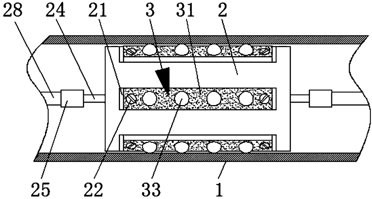
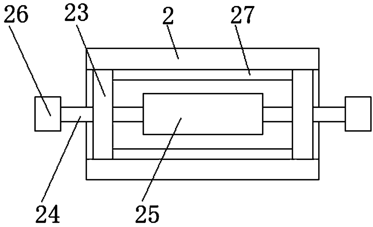
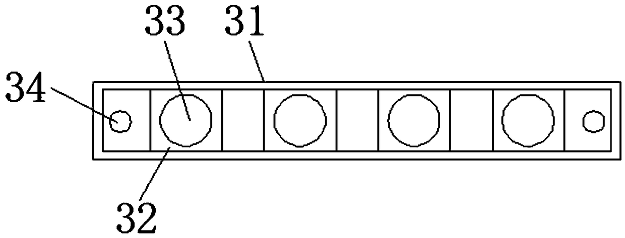
[0024] see Figure 1-6 , a composite sucker rod centralizer, including an outer cylinder 2 that is movably fitted inside a sucker pipe 1 and an eccentric wear mechanism 3 fixedly installed on the surface of the outer cylinder 2. Six mounting grooves 21 are provided on the surface of the outer cylinder 2. The inner wall of cylinder 2 is provided with oil guide holes 4, the number of oil guide holes 4 is six, and the six oil guide holes 4 are spirally and symmet...


PUM


Abstract

The invention relates to the field of a petroleum exploitation tool and discloses a composite oil sucking rod centralizer. The composite oil sucking rod centralizer includes an outer cylinder movablysleeved inside an oil sucking pipe and an eccentric wear mechanism fixedly mounted on the surface of the outer cylinder, wherein the surface of the outer cylinder is provided with six mounting grooves, the six mounting grooves are symmetrically distributed on the surface of the outer cylinder, and the eccentric wear mechanism includes support sleeves movably sleeved inside the mounting grooves ina rotation mode. The composite oil sucking rod centralizer is advantaged in that an inner wall of the oil sucking pipe is contacted by the outer cylinder for protection, the oil sucking rod is connected with the middle of the outer cylinder, when the oil sucking rod moves in the oil sucking pipe, the oil passes through an inner portion of the outer cylinder instead of the part between an outer cylinder and an oil pipe in the prior art, the distance between the oil sucking rod and the inner wall of the oil sucking pipe is increased, when the oil sucking rod is bent, direct contact and partial grinding of the position of the oil sucking rod and the inner wall of the oil sucking pipe are avoided, and a problem of reduction of the use effect of the oil sucking rod centralizer is solved.

Description

technical field [0001] The invention relates to the field of oil extraction tools, in particular to a composite sucker rod centralizer. Background technique [0002] The sucker rod centralizer is an essential tool in the process of oil exploitation. The sucker rod is protected by the centralizer. When the sucker rod moves up and down in the oil pipe, the sucker rod is elastically deformed, and the rod and the oil The pipe wall is prone to friction, and the sucker rod is easy to break off. The sucker rod centralizer has strong flexibility, and it contacts with the inner wall of the oil pipe, which can reduce the friction between the rod and the pipe and increase the oil production life of the pumping unit. [0003] However, the existing sucker rod centralizer and the inner wall of the oil pipe generally leave as large an oil passage as possible so that the oil can pass through, so that the outer diameter of the centralizer is much smaller than the inner diameter of the oil pi...

Claims


Application Information

Patent Timeline
Patent Type & Authority Applications(China)
IPC IPC(8): E21B17/10
CPCE21B17/1057E21B17/1071
Inventor 张淞源张虎
Owner DAQING TIANDEZHONG PETROLEUM SCI & TECH CO LTD
Why Eureka
Try Eureka