Fin and heat exchanger provided with same

A technology of heat exchangers and fins, applied in the field of fins and heat exchangers with them, can solve the problems of affecting air flow, affecting the smooth drainage of fins, and excessive condensation water, so as to facilitate drainage and improve heat exchange Efficiency, impact reduction effect

Pending Publication Date: 2019-01-11
GREE ELECTRIC APPLIANCES INC OF ZHUHAI
View PDF0 Cites 1 Cited by
  • Summary
  • Abstract
  • Description
  • Claims
  • Application Information

AI Technical Summary

Problems solved by technology

[0004] Due to the structural limitation of the grooved fin itself, in order to ensure the fin pitch during production, a fin positioning mechanism for determining the fin pitch must be installed on the fin. The fin positionin

Method used


Image

  • Fin and heat exchanger provided with same
  • Fin and heat exchanger provided with same
  • Fin and heat exchanger provided with same

Examples


Example Embodiment

[0034] Example 1:

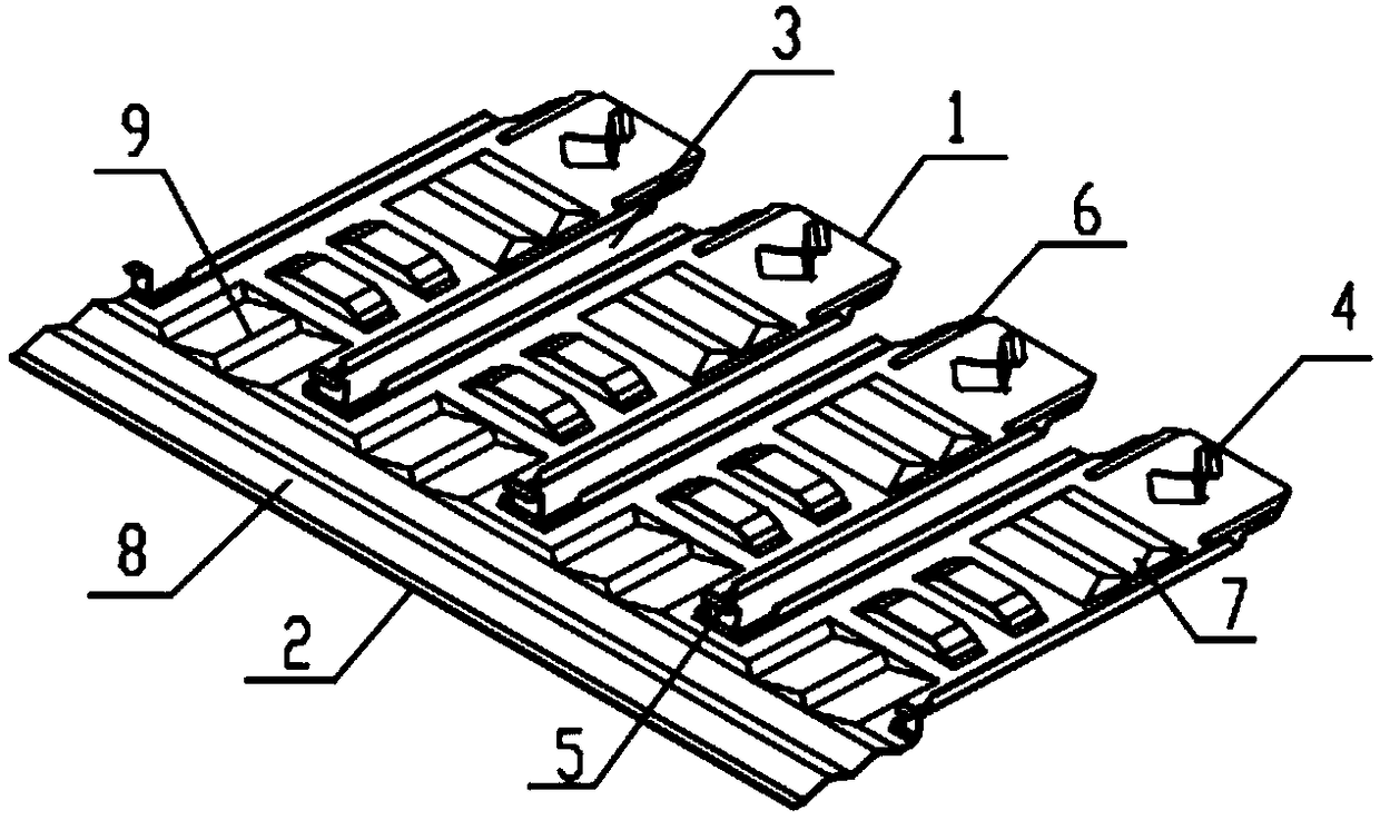
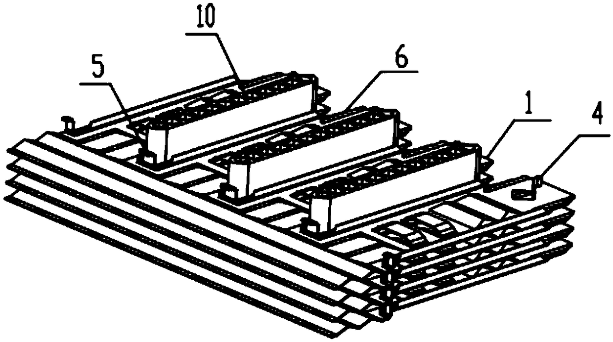
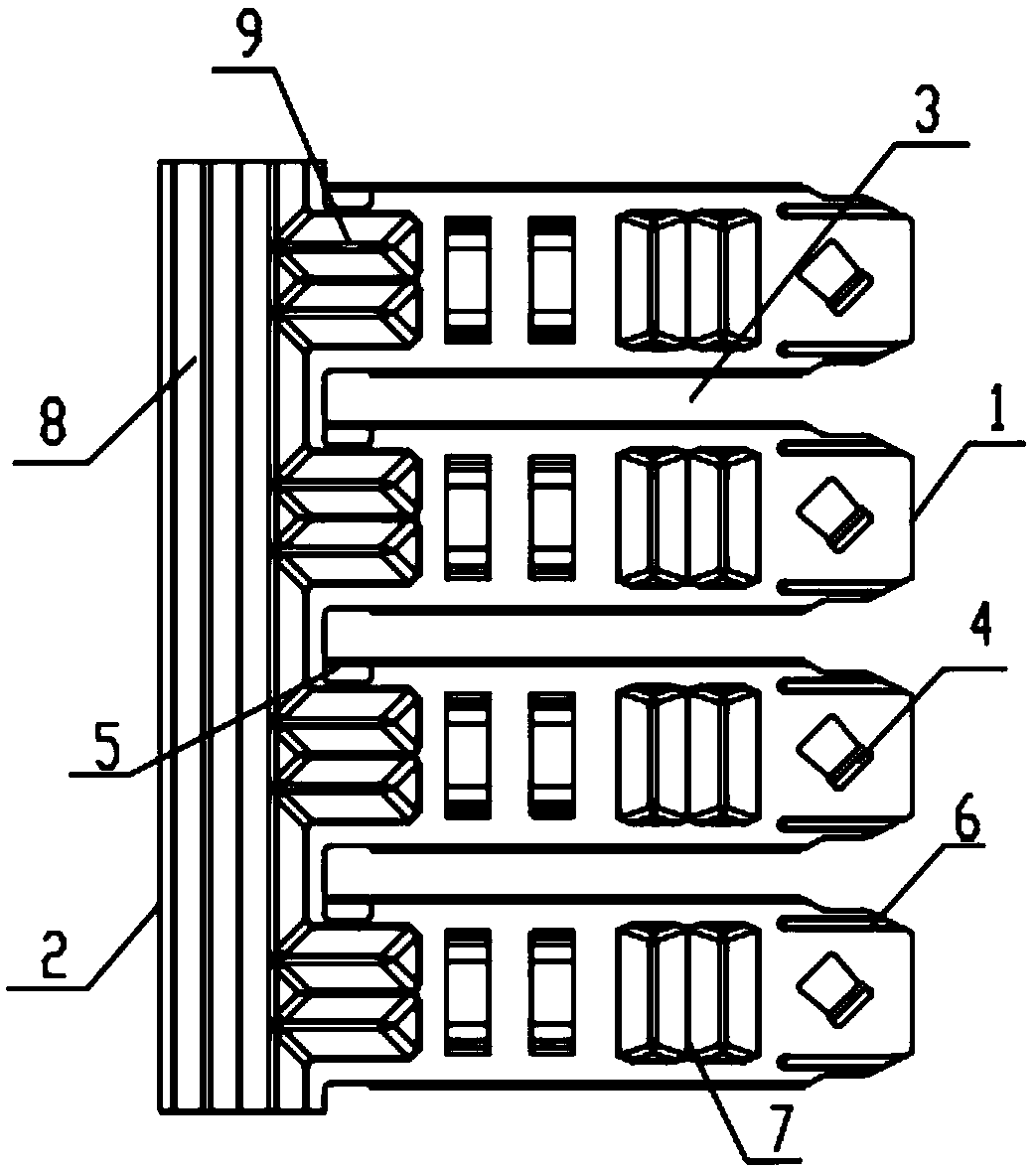
[0035] Please refer to figure 1 -3. This embodiment provides a fin and a heat exchanger containing it. One end of the fin is the upwind side 1, the end of the fin opposite to the upwind side 1 is the downwind side 2, and the upwind side 1 is provided with one or more A flat tube groove 3 extending toward the downwind side 2, and the flat tube groove 3 is used to install the flat tube 10;

[0036] The fins are provided with a first positioning structure 4 and a second positioning structure 5 for stacking to form a pitch. The first positioning structure 4 is arranged on the windward side 1, and the second positioning structure 5 is arranged on the flat tube groove 3 facing the leeward side 2. One side or set in the flat tube groove 3.

[0037] The second positioning mechanism is located on the downwind side 2. After the flat tube groove 3 is installed with the flat tube 10, the second positioning structure 5 is located on the leeward side of the flat tube 10. The s...


PUM


Abstract

The invention relates to the technical field of heat exchange, in particular to a fin and a heat exchanger provided with the same. One end of the fin is a windward side. The end, opposite to the windward side, of the fin is a leeward side. The windward side is provided with one or more flat pipe grooves extending toward the leeward side. The flat pipe grooves are used for installing flat pipes. The fin is provided with first locating structures and second locating structures which are used for forming fin distance in a stacked mode. The first locating structures are arranged on the windward side. The second locating structures are arranged on the sides, toward the leeward side, of the flat pipe grooves or are arranged in the flat pipe grooves. The heat exchanger comprises flat pipes and fins. The flat pipes are pressed into flat pipe grooves. Second locating structures are located on the leeward side of the flat pipes or are arranged on the side faces of the flat pipes to be attached to the flat pipes. Through the second locating structures, the influence on airflow is reduced, fin wind resistance is reduced, fin water drainage is facilitated, and heat exchange efficiency of the heat exchanger is improved.

Description

technical field [0001] The invention relates to the technical field of heat exchange, in particular to a fin and a heat exchanger having the same. Background technique [0002] Microchannel heat exchanger is a new type of high-efficiency heat exchanger, which has the advantages of high heat transfer efficiency, small size, light weight, and less charge. [0003] The fins of the traditional single-cooling microchannel heat exchanger are rolled into a wave shape by a rolling mill, and then brazed between the upper and lower flat tubes. [0004] Due to the limitation of the structure of the slot-type fin itself, in order to ensure the pitch of the fins during production, a fin positioning mechanism for determining the pitch must be installed on the fins. The fin positioning mechanism affects the smooth drainage of the fins, especially in the The downwind side of the fins affects the airflow, and there is more condensed water, which seriously affects the working efficiency of t...

Claims


Application Information

Patent Timeline
IPC IPC(8): F28F1/32
CPCF28F1/325F28F2215/08F28F2215/10
Inventor 朱守朝张有林薛震吴迎文
Owner GREE ELECTRIC APPLIANCES INC OF ZHUHAI
Why Eureka
Try Eureka