An electrical connection device for a circuit board

A technology for electrical connection devices and circuit boards, which is applied to components of connection devices, devices to prevent wrong connections, connections, etc. It can solve problems such as poor contact of conductive parts of circuit boards, terminal damage, and weakened elasticity, so as to prevent terminal The effect of metal fatigue

Active Publication Date: 2019-01-11
QINGDAO UNIV OF SCI & TECH
View PDF5 Cites 3 Cited by
  • Summary
  • Abstract
  • Description
  • Claims
  • Application Information

AI Technical Summary

Problems solved by technology

[0002] Circuit boards are widely used in electronic equipment, and they are usually electrically connected to multiple terminals in electrical connectors to realize signal transmission. The existing circuit board connection devices have the following problems: when inserting a circuit board, it is easy to be affected by the direction The deviation leads to the damage of the terminal; and most electronic equipment is in a state of frequent movement, and the circuit board is easy to come out of the electrical connector due to vibration and other reasons, resulting in signal interruption. In addition, the terminals in the electrical connector usually rely on their own elasticity and The conductive part of the circuit board is in contact, but after several times of plugging and unplugging, the metal forming the terminal will have metal fatigue, weakened elasticity, and even poor contact with the conductive part of the circuit board

Method used


Image

  • An electrical connection device for a circuit board
  • An electrical connection device for a circuit board
  • An electrical connection device for a circuit board

Examples


Embodiment Construction

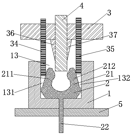
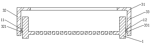
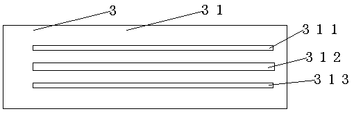
[0020] An electrical connection device for a circuit board, comprising a housing 1, a terminal 2, a crimping device 3, a circuit board 4 and a bottom PCB board 5, the housing 1 includes side walls and a bottom wall, and latching devices are arranged on the outside of the left and right side walls 11, 12, the surrounding side walls surround the terminal accommodating portion 13, several terminals 2 are arranged in the terminal accommodating portion 13, the terminal 2 is located in the middle of the terminal accommodating portion, the terminal 2 includes a U-shaped body portion 21 and is connected to the U The bottom wall of the housing 1 is provided with a hole, and the welding portion 22 of the terminal 2 is welded on the bottom PCB board 5 after passing through the hole in the bottom wall. The U-shaped body portion 21 of the terminal 2 includes a second A contact 211 and a second contact portion 212, the opposite sides of the first contact 211 and the second contact portion 21...


PUM


Abstract

The invention discloses an electrical connection device of a circuit board, including a housing, a terminal, a crimping device, a circuit board and a bottom PCB, the terminal includes a convex arc portion in electrical contact with the circuit board, the crimping device includes a flat plate portion and a vertical portion extending from the left and right sides of the flat plate portion, three bar-shaped holes penetrating through the plate part are arranged in parallel on the plate part, an elastic body is fixedly arranged on the two strip-shaped holes close to the outer side, one end of the elastomer is a fixed end, the other end extends between the outside of the terminal and the side wall of the housing, at a lower middle position of the flat plate portion, a lower portion of the intermediate bar hole is provided with a first clip body and a second clip body, and the electrical connection device of the circuit board can realize stable electrical contact between the circuit board andthe terminal, and can prevent poor contact caused by poor elasticity after the terminal is used for a long time.

Description

technical field [0001] The invention relates to the field of electrical connection, in particular to an electrical connection device for a circuit board. Background technique [0002] Circuit boards are widely used in electronic equipment, and they are usually electrically connected to multiple terminals in electrical connectors to realize signal transmission. The existing circuit board connection devices have the following problems: when inserting a circuit board, it is easy to be affected by the orientation The deviation leads to the damage of the terminal; and most electronic equipment is in a state of frequent movement, and the circuit board is easy to come out of the electrical connector due to vibration and other reasons, resulting in signal interruption. In addition, the terminals in the electrical connector usually rely on their own elasticity and The conductive parts in the circuit board are in contact, but after several times of plugging and unplugging, the metal f...

Claims


Application Information

Patent Timeline
Patent Type & Authority Applications(China)
IPC IPC(8): H01R12/72H01R12/73H01R13/193H01R13/627H01R13/639H01R13/64H01R13/02
CPCH01R12/721H01R12/737H01R13/02H01R13/193H01R13/6275H01R13/639H01R13/64
Inventor 曾宪奎陈明同曾佳赵羽劲朱维浩
Owner QINGDAO UNIV OF SCI & TECH
Why Eureka
Try Eureka