Automatic fire extinguishing device for photovoltaic junction box

A photovoltaic combiner box and automatic fire extinguishing technology, which is applied in fire rescue and other directions, can solve the problems of increasing the number of junction box connections, increasing the possibility of a photovoltaic combiner box fire, and other environmental factors, so as to improve stability, The effect of improving safety

Pending Publication Date: 2019-01-15
佛山市智阳能源有限公司
View PDF10 Cites 3 Cited by
  • Summary
  • Abstract
  • Description
  • Claims
  • Application Information

AI Technical Summary

Problems solved by technology

The construction of electronic components will definitely increase the number of wiring inside the combiner box, thereby increasing the possibility of a fire in the photovoltaic combiner box, and the overall safety of the photovoltaic combiner box is relatively reduced.
Moreover, since a fire in a photovoltaic combiner box is not necessarily caused by a short circuit of the wires or an overload current, it may be caused by other environmental factors, and the traditional automatic circuit breaker can only be disconnected when the overcurrent reaches a certain threshold, and other occurrences cannot be avoided. The fire caused by factors melts the wire sheath and causes a short circuit and causes a secondary fire

Method used


Image

  • Automatic fire extinguishing device for photovoltaic junction box
  • Automatic fire extinguishing device for photovoltaic junction box
  • Automatic fire extinguishing device for photovoltaic junction box

Examples


Embodiment Construction

[0020] The present invention provides an automatic fire extinguishing device for a photovoltaic combiner box. In order to make the purpose, technical solution and effect of the present invention clearer and clearer, the present invention will be further described in detail below with reference to the accompanying drawings and examples. It should be understood that the specific embodiments described here are only used to explain the present invention, and are not intended to limit the protection scope of the present invention.

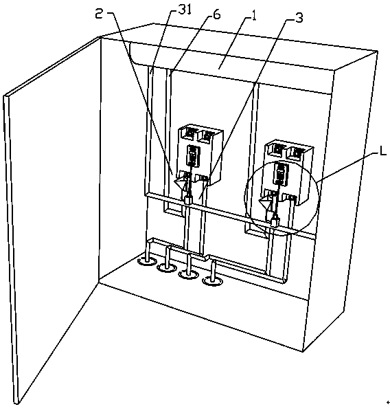
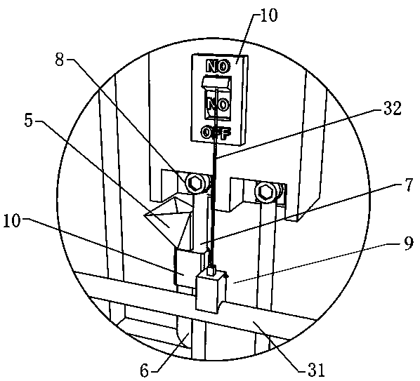
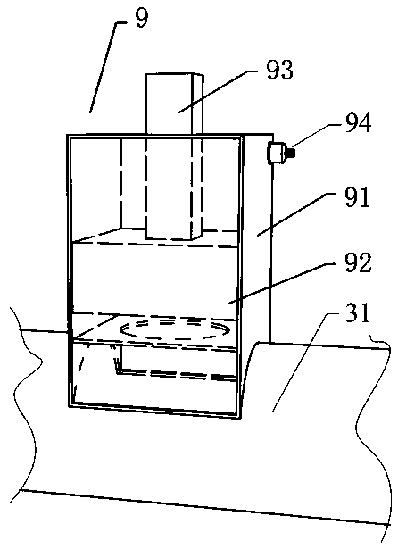
[0021] see Figure 1-Figure 3 , the present invention provides an automatic fire extinguishing device for a photovoltaic combiner box, including a gas storage tank 1 arranged on the photovoltaic combiner box, a fire extinguishing mechanism 2 and a circuit breaker 3 arranged in the photovoltaic combiner box, the gas storage tank 1 is equipped with gas for fire extinguishing. The fire extinguishing mechanism 1 includes a fire extinguishing nozzle 5, a low...


PUM


Abstract

The invention discloses an automatic fire extinguishing device for a photovoltaic junction box. The automatic fire extinguishing device for the photovoltaic junction box comprises a gas storage tank,a fire extinguishing mechanism and a disconnecting mechanism which are arranged on the photovoltaic junction box, wherein the gas storage tank is filled with a gas for extinguishing fire, and the fireextinguishing mechanism comprises a fire extinguishing nozzle, a low-melting-point metal sealing plug, and a heat conducting exhaust pipe; one end of the heat conducting exhaust pipe is connected with the gas storage tank, and the other end of the heat conducting exhaust pipe is connected with the fire extinguishing nozzle; the low-melting-point metal sealing plug is arranged in the heat conducting exhaust pipe, and the heat conducting exhaust pipe is connected with a wire connected to a breaker in a heat conducting way. When the photovoltaic junction box is short-circuited, the wiring terminal of the breaker generates a high temperature, so that the line temperature rises. After the heat conducting exhaust pipe is subjected to the heat conduction of the line, the low-melting-point metalsealing plug is slightly melted in a short time; meanwhile, the low-melting-point metal sealing plug is pushed out by the gas pressure provided by the gas storage tank, and then the fire extinguishinggas is ejected from the fire extinguishing nozzle, so that the fire source can be quickly and effectively extinguished, and the stability of automatic fire extinguishing can be improved.

Description

technical field [0001] The invention relates to the field of electrical fire extinguishing, in particular to an automatic fire extinguishing device for a photovoltaic combiner box. Background technique [0002] At present, the photovoltaic combiner boxes on the market already have the functions of confluence, lightning protection and monitoring, and can also detect the temperature and humidity of the combiner box, as well as failure alarm, data collection, wireless data transmission and other functions. Therefore, this makes the wiring of the photovoltaic DC combiner box more and more complex, and also increases the possibility of fire in the photovoltaic DC combiner box. At present, the photovoltaic combiner boxes with automatic fire extinguishing function are automatic fire extinguishing systems built with electronic components such as infrared sensors, temperature sensors, and control chips. The construction of electronic components will definitely increase the number of...

Claims


Application Information

Patent Timeline
Patent Type & Authority Applications(China)
IPC IPC(8): A62C3/16A62C37/11
CPCA62C3/16A62C37/11
Inventor 潘松振
Owner 佛山市智阳能源有限公司
Why Eureka
Try Eureka