Continuous stamping and forming device for filter filter safety valve gland

A technology of stamping forming and safety valve, which is applied in the direction of storage device, feeding device, positioning device, etc., can solve the problems of easy production of defective products, low efficiency, breakage, etc., and achieve the improvement of production efficiency, production efficiency, and qualification rate improvement Effect

Active Publication Date: 2019-05-07
佛山市豹王滤芯制造有限公司
View PDF7 Cites 0 Cited by
  • Summary
  • Abstract
  • Description
  • Claims
  • Application Information

AI Technical Summary

Problems solved by technology

Manual processing is time-consuming, labor-intensive, and inefficient. In addition, during the manual riveting process, the riveting is not tight or the metal sheet is likely to be broken, which is prone to produce defective products. According to calculations, a factory uses manual processing to produce oil filter safety valve glands. , the average processing volume of each skilled worker is 65 pieces / hour, and the qualified rate is 78%. With the increasing labor costs and the requirements of modern processing and production, it has become more and more difficult for workers to produce manually to meet the safety of oil filtration. Processing requirements for valve glands

Method used


Image

  • Continuous stamping and forming device for filter filter safety valve gland
  • Continuous stamping and forming device for filter filter safety valve gland
  • Continuous stamping and forming device for filter filter safety valve gland

Examples


Embodiment

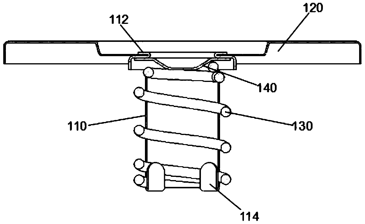
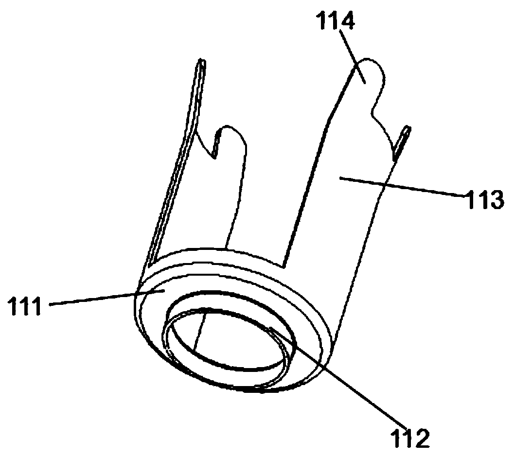
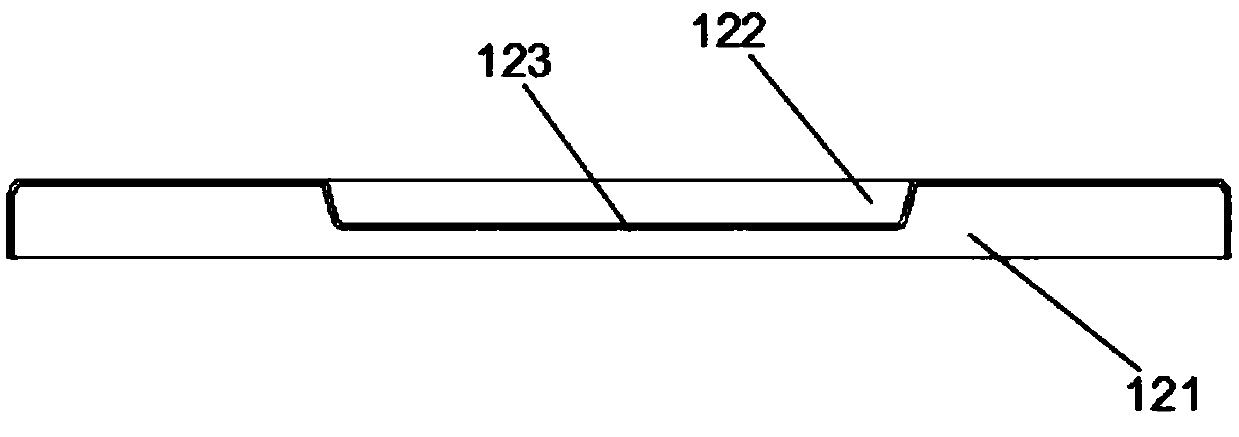
[0041] Embodiment: A continuous stamping and forming device for filter filter safety valve cover.

[0042] refer to Figure 1 to Figure 24 As shown, a filter filter safety valve gland continuous stamping forming device, including: frame 1; ring track 2 installed on frame 1; mounted on the rear end of frame 1 and used to drive ring track 2 The driving device of operation, described driving device comprises mounting base, drive motor 3, transmission gear 4 and coupling, described driving motor 3 is fixed on the mounting base, and driving motor 3 passes through the transmission of transmission gear 4 through coupling Shaft connection, the transmission gear 4 meshes with the crawler belt 2, and the drive motor 3 is a servo motor, which drives the transmission gear 4 to rotate and then drives the endless crawler belt 2 to continue running;

[0043] The continuous forming device also includes a plurality of stamping parts placement columns 5 fixed at intervals in parallel on the en...


PUM

PropertyMeasurementUnit
angleaaaaaaaaaa

Abstract

The invention provides a continuous punch forming device of a filter cleaner filtration safety valve gland. The device comprises a rack, an annular caterpillar band arranged on the rack, a driving device arranged at the rear end of the rack and used for driving the annular caterpillar band to operate, multiple punch part putting columns fixed to the annular caterpillar band at intervals in parallel, a first punch mechanism, a second punch mechanism, a third punch mechanism and a fourth punch mechanism, punch part fixing discs are arranged between two adjacent punch part putting columns, and the first punch mechanism, the second punch mechanism, the third punch mechanism and the fourth punch mechanism are sequentially arranged on the rack at intervals side by side in the running direction of the caterpillar band. According to the continuous punch forming device of the filter cleaner filtration safety valve gland, continuous punch forming of the engine oil filter safety valve gland can be achieved, production efficiency of the engine oil filter safety valve gland can be greatly improved, the forming quality of the engine oil filter safety valve gland can be improved, and compared with traditional manual machining manner, the per capita production efficiency is improved by 226%, and the yield is improved by 20%.

Description

technical field [0001] The invention relates to the technical field of machine oil filter safety valve processing equipment, in particular to a continuous stamping and forming device for filter filter safety valve glands. Background technique [0002] The oil filter safety valve is an emergency device that is set when the filter element is blocked or the flow is insufficient, and the pressure is opened. After the oil filter safety valve is opened, the oil is not filtered by the filter element, but directly enters the engine through the safety valve from the filter element cavity, so as to prevent the engine from being damaged due to insufficient fuel or lubricating oil. Among them, the gland of the oil filter safety valve is a very important component in the oil filter safety valve, and the quality of the gland processing directly determines the quality of the oil filter safety valve. figure 1 The common structure of the oil filter safety valve cover includes a spring sleev...

Claims


Application Information

Patent Timeline
Patent Type & Authority Patents(China)
IPC IPC(8): B21D39/00B21D43/00
CPCB21D39/00B21D43/003
Inventor 黄兆强何国安罗雄章李细和
Owner 佛山市豹王滤芯制造有限公司
Why Eureka
Try Eureka