
A machine tool

A technology of machine tools and cutting tools, applied in the field of machine tools, can solve problems such as cuts, achieve the effects of reducing danger, simple structure, and protecting personal safety

Inactive Publication Date: 2019-01-15
台州池泽科技有限公司
View PDF0 Cites 2 Cited by
  • Summary
  • Abstract
  • Description
  • Claims
  • Application Information

AI Technical Summary

Problems solved by technology

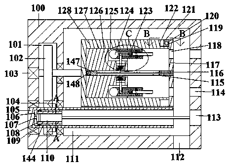
[0002] Existing machines for cutting wood often expose the knives to the air, which not only causes tragedies due to improper operation by the user during use, but also easily causes cuts when the machine is being transported or passed by the machine when it is not in use. danger, this device effectively solves this problem

Method used


Image

  • A machine tool
  • A machine tool
  • A machine tool

Examples


Embodiment Construction

[0021] All features disclosed in this specification, or steps in all methods or processes disclosed, may be combined in any manner, except for mutually exclusive features and / or steps.

[0022] Any feature disclosed in this specification (including any appended claims, abstract and drawings), unless expressly stated otherwise, may be replaced by alternative features which are equivalent or serve a similar purpose. That is, unless expressly stated otherwise, each feature is one example only of a series of equivalent or similar features.

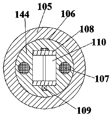
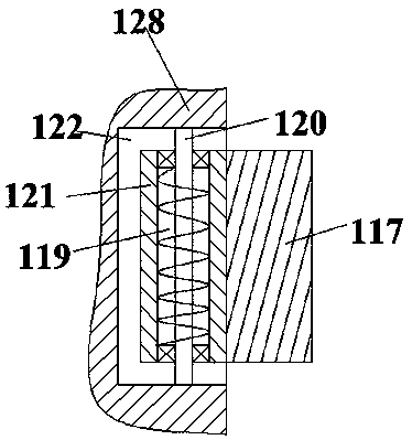
[0023] like Figure 1-6 As shown, for the convenience of description, the orientations mentioned below are stipulated as follows: the directions of up, down, left, right, front, back and figure 1The projection relationship itself has the same direction of up, down, left, right, front, and back. A machine tool of the present invention includes a worktable 100 fixed on the ground, a work cavity 111 is fixed in the worktable 100, and a tool is s...


PUM


Abstract

A machine tool is disclosed. The machine tool includes a workbench fixedly disposed on the ground. A translation cavity having a downward opening is fixedly disposed in the workbench. The lower end wall of the translation cavity is provided with and communicates with a working cavity in the workbench. The right end wall of the working cavity is provided with and communicates with an access port inthe workbench and communicating with the outer space. The machine tool is simple in structure and convenient to use. Rusty metal is subjected to rust removing and made rust-free for long time throughfriction or anti-rust liquid spraying. The machine tool is provided with a plurality of buffer configurations and can adapt to rusty metal with irregular shapes, thus improving reliability of the machine tool. Steps are simplified by the machine tool and co-movement performance is increased to achieve inward movement of the rusty metal along with rotation to perform a next step, thus improving the co-movement performance.

Description

technical field [0001] The invention relates to the field of machining, in particular to a machine tool. Background technique [0002] Existing machines for cutting wood often expose the knives to the air, which not only causes tragedy due to improper operation by the user during use, but also easily causes cuts when the machine is being transported or passed by the machine when it is not in use. danger, this device effectively solves this problem. Contents of the invention [0003] The object of the present invention is to provide a machine tool capable of overcoming the above-mentioned drawbacks of the prior art. [0004] According to the present invention, a machine tool of the equipment of the present invention includes a workbench fixed on the ground, a work chamber is fixed in the workbench, a tool table is fixed in the work chamber, and a tool table is fixed in the work table. There is a tool cavity with an opening facing right, and a middle block is fixed on the ...

Claims


Application Information

Patent Timeline
Patent Type & Authority Applications(China)
IPC IPC(8): B27C5/02B27C5/06
CPCB27C5/02B27C5/06
Inventor 孙诗妍
Owner 台州池泽科技有限公司
Learn More