Eureka AIR delivers breakthrough ideas for toughest innovation challenges, trusted by R&D personnel around the world.

Continuous air cooling device for plywood

An air-cooling device and plywood technology, applied to other plywood/plywood appliances, wood processing appliances, manufacturing tools, etc., can solve the problem of low natural cooling efficiency and achieve high efficiency

Active Publication Date: 2019-01-15
盱眙福盛木业有限公司
View PDF10 Cites 2 Cited by
  • Summary
  • Abstract
  • Description
  • Claims
  • Application Information

AI Technical Summary

Problems solved by technology

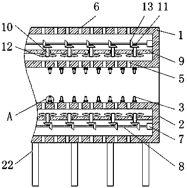
[0003] The purpose of the invention is to solve the problem of low efficiency of natural cooling in the prior art, and propose a continuous air cooling device for plywood

Method used


Image

  • Continuous air cooling device for plywood
  • Continuous air cooling device for plywood
  • Continuous air cooling device for plywood

Examples


Embodiment Construction

[0019] The following will clearly and completely describe the technical solutions in the embodiments of the present invention with reference to the accompanying drawings in the embodiments of the present invention. Obviously, the described embodiments are only some, not all, embodiments of the present invention.

[0020] In describing the present invention, it should be understood that the terms "upper", "lower", "front", "rear", "left", "right", "top", "bottom", "inner", " The orientation or positional relationship indicated by "outside", etc. is based on the orientation or positional relationship shown in the drawings, and is only for the convenience of describing the present invention and simplifying the description, rather than indicating or implying that the referred device or element must have a specific orientation, so as to Specific orientation configurations and operations, therefore, are not to be construed as limitations on the invention.

[0021] refer to Figure ...


PUM


Abstract

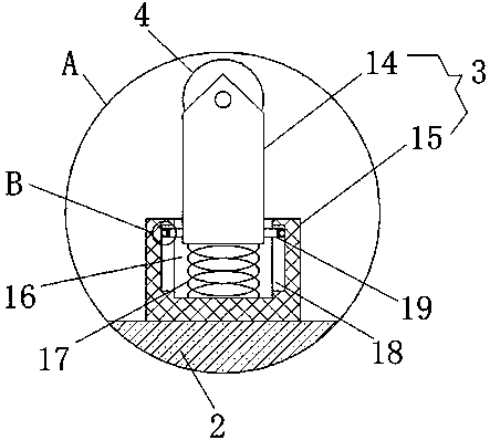
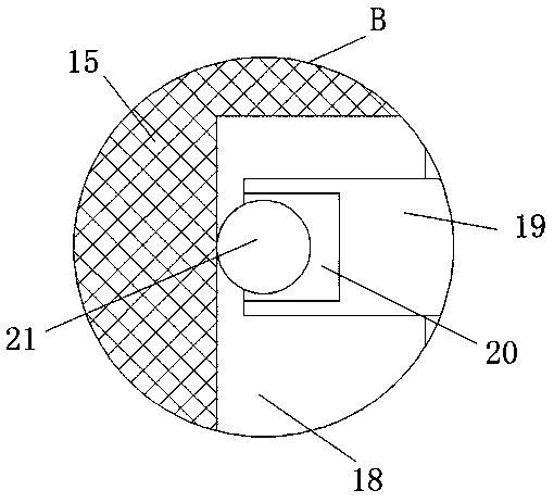
The invention discloses a continuous air cooling device for plywood. The continuous air cooling device comprises an upper air cooling box and a lower air cooling box; the upper air cooling box is located directly above the lower air cooling box; the opposite outer box walls of the upper air cooling box and the lower air cooling box are fixedly and uniformly connected with a plurality of supportingcomponents linearly at equal intervals; the supporting components are provided with pulleys; a vent hole is formed between any two adjacent supporting components; the vent holes are formed in the corresponding opposite box walls of the upper air cooling box and the lower air cooling box; air outlets which are corresponding to the vent holes, are formed in the box walls of the upper air cooling box and the lower air cooling box which are far away from each other; the vertical inner box walls of the upper air cooling box and the lower air cooling box at the same side are fixedly provided with two motors respectively; the output ends of the motors are connected with rotating rods through couplings; and horizontally-arranged fixing plates are installed in the upper air cooling box and the lower air cooling box; and the fixing plates are arranged between the two motors. According to the continuous air cooling device for plywood of the invention, two sets of blades with the same rotation direction are adopted, so that the speed of the heat dissipation of the plywood is higher.

Description

technical field [0001] The invention relates to the technical field of plywood production, in particular to a continuous air cooling device for plywood. Background technique [0002] Plywood is a three-layer or multi-layer wood material glued together with adhesives. Plywood has a wide range of applications and is used in many fields such as building materials, packaging, and ships. At present, most plywood manufacturers produce plywood when they are finished. Just put it in the warehouse for natural cooling, although natural cooling can also achieve the purpose of cooling, but the cooling rate is slower, and the cooling rate is slower when the weather is hotter. Contents of the invention [0003] The purpose of the present invention is to solve the problem of low efficiency of natural cooling in the prior art, and propose a continuous air cooling device for plywood. [0004] In order to achieve the above object, the present invention adopts the following technical soluti...

Claims


Application Information

Patent Timeline
Patent Type & Authority Applications(China)
IPC IPC(8): B27D5/00
CPCB27D5/00
Inventor 刘航黄基成
Owner 盱眙福盛木业有限公司
Why Eureka
Eureka Blog
Learn More