Cooling System for an Aircraft, Aircraft Comprising the Cooling System and Cooling Method

a cooling system and aircraft technology, applied in the direction of machines/engines, fuselages, transportation and packaging, etc., can solve the problems of limited cooling capacity of fuel, increased costs, and reduced cooling capacity of fuel available for signature reduction, so as to increase the total resistance of aircraft, increase the effect of gas radiation, and increase the temperature of exhaust gas

Inactive Publication Date: 2008-10-09
VOLVO AERO CORP
View PDF21 Cites 7 Cited by
  • Summary
  • Abstract
  • Description
  • Claims
  • Application Information

AI Technical Summary

Benefits of technology

[0013]According to a preferred embodiment of the method, the coolant is taken to the jet engine for releasing heat to a flow of gas in the jet engine. This results in a direct transmission, or transfer, of the infrared radiation from the component that is less advantageous, as far as detection is concerned, to the more advantageous exhaust gases.
[0014]According to an alternative to the previous embodiment, ram air is taken in and utilized as the cool

Problems solved by technology

This results in additional costs, for example, due to the fact that the fuel tanks must/should be insulated and there should be systems for monitoring the fuel temperature.
In addition, the cooling capacity of the fuel is limited.
The cooling capacity of the fuel can also be required for other purp

Method used


Image

  • Cooling System for an Aircraft, Aircraft Comprising the Cooling System and Cooling Method
  • Cooling System for an Aircraft, Aircraft Comprising the Cooling System and Cooling Method
  • Cooling System for an Aircraft, Aircraft Comprising the Cooling System and Cooling Method

Examples


Embodiment Construction

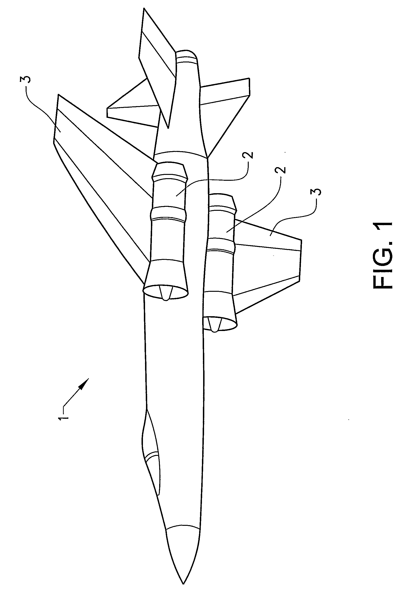
[0020]FIG. 1 shows an aircraft 1 in a perspective view from below. A jet engine 2 is mounted under each wing 3.

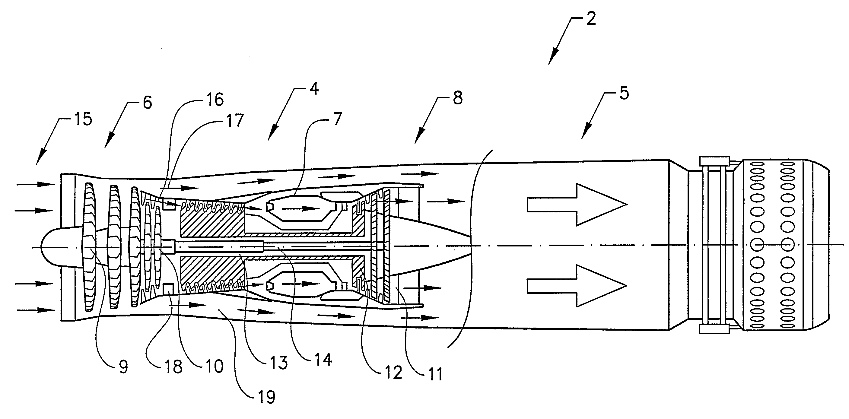
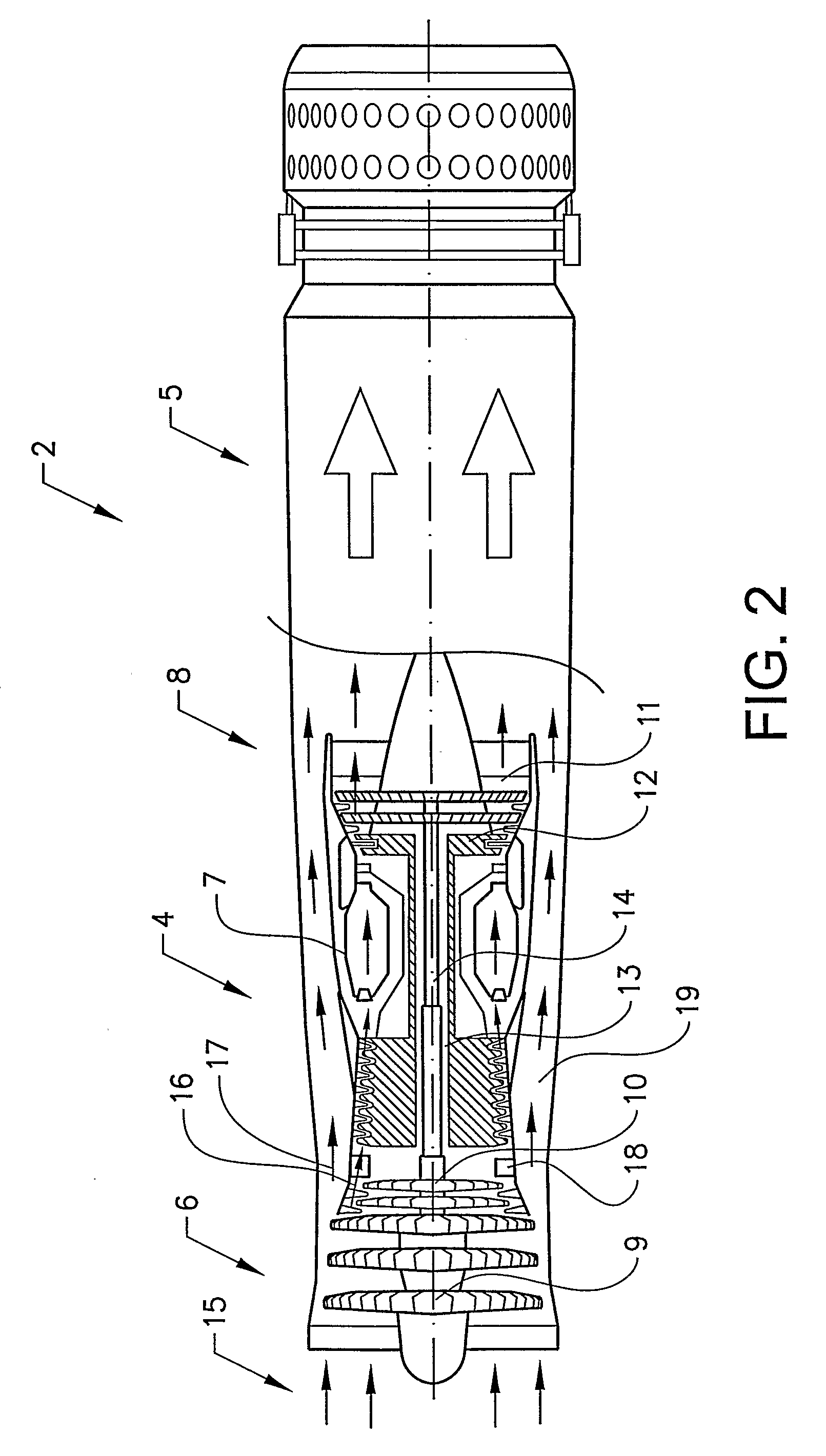
[0021]FIG. 2 shows one of the jet engines 2 in a cross-sectional view. The jet engine 2 comprises two main parts, a gas generator 4 and an afterburner 5. The gas generator 4 is of the double-flow type and has twin rotors.

[0022]The jet engine comprises a compressor section 6 for compression of the incoming air, a combustion chamber 7 for combustion of the compressed air and a turbine section 8 arranged after the combustion chamber, which turbine section is connected to the compressor section in such a way that it can rotate in order to drive this by means of the energy-rich gases from the combustion chamber. The compressor section 6 comprises a low-pressure part 9, or fan, and a high-pressure part 10. The turbine section 8 comprises a low-pressure part 11 and a high-pressure part 12. The high-pressure compressor 10 is attached to the high-pressure turbine 12 via a first shaf...


PUM


Abstract

A cooling system for an aircraft includes a cooling circuit for transporting a coolant, with the cooling circuit running to a component in the aircraft that is heated up during flying in order to take up heat from the heated-up component via the coolant. The cooling circuit runs to a jet engine for propulsion of the aircraft in order to release heat to a flow of gas in the jet engine via the coolant.

Description

BACKGROUND AND SUMMARY[0001]The present invention relates to a cooling system for an aircraft, comprising a cooling circuit for transportation of a coolant, with the cooling circuit running to a component in the aircraft that becomes heated during flying in order to take up heat from the heated-up component via the coolant.[0002]The invention also relates to a cooling method for an aircraft and an aircraft comprising the cooling system.[0003]Protecting an aircraft against an attack by giving the aircraft a low so-called signature is already known. By signature is meant, in this context, the contrast against the background. An aircraft should, for example, have a low signature with regard to infrared radiation (IR). Hot structures and hot exhaust gases give rise to an IR signature. External projecting surfaces or edges on the fuselage or wings of the aircraft can become hot during flying as a result of aerodynamic friction and can then give rise to an IR signature. Examples of such s...

Claims


Application Information

Patent Timeline
IPC IPC(8): F02K11/00F02K99/00
CPCB64C1/38
Inventor MARTENSSON, HANSHELLGREN, ANDERS
Owner VOLVO AERO CORP
Why Eureka
Try Eureka