Supercharge Your Innovation With Domain-Expert AI Agents!

Demoulding device for ceramic sanitary ware grouting line end mould and demolding method thereof

A demoulding device and grouting technology, applied in the direction of unloading device, manufacturing tools, etc., can solve the problems of surface damage of the head die, slow production efficiency, high use height, achieve accurate demoulding and mold clamping, improve production efficiency, The effect of increasing the practical effect

Pending Publication Date: 2019-01-15
FOSHAN UNIVERSITY
View PDF2 Cites 0 Cited by
  • Summary
  • Abstract
  • Description
  • Claims
  • Application Information

AI Technical Summary

Problems solved by technology

Nowadays, with the continuous improvement of ceramic production quality and production efficiency, it is not easy and complete to separate the head mold from the mold when the demoulding operation is still performed manually.
In addition, when it is produced in large quantities, due to the use of manpower, the production efficiency is very slow, which is not in line with economic benefits; at the same time, the diversity of ceramic products leads to inconsistent heights of the body, which easily damages the surface of the head mold, and the production pass rate of ceramic products low
At present, there are also automatic demoulding devices, but this type of device has a high use height, resulting in poor versatility, large space occupation, and its structure is not compact and does not have the function of mold clamping. Therefore, it is necessary to provide a new technical solution to overcome the above problems. defect

Method used


Image

  • Demoulding device for ceramic sanitary ware grouting line end mould and demolding method thereof
  • Demoulding device for ceramic sanitary ware grouting line end mould and demolding method thereof
  • Demoulding device for ceramic sanitary ware grouting line end mould and demolding method thereof

Examples


Embodiment Construction

[0023] The following will clearly and completely describe the technical solutions in the embodiments of the present invention with reference to the accompanying drawings in the embodiments of the present invention. Obviously, the described embodiments are only some, not all, embodiments of the present invention. Based on the embodiments of the present invention, all other embodiments obtained by persons of ordinary skill in the art without creative work, any modifications, equivalent replacements, improvements, etc., shall be included in the protection scope of the present invention Inside.

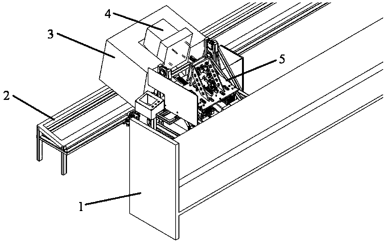
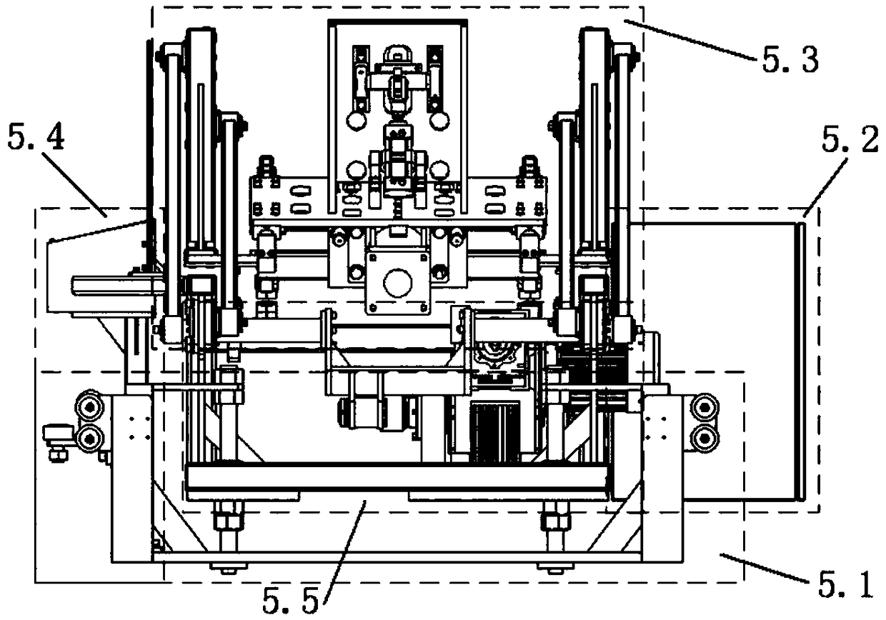
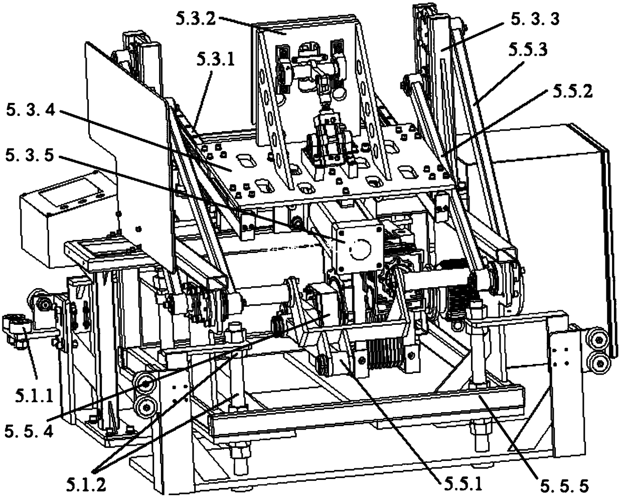
[0024] like figure 1 , figure 2 and image 3 As shown, a ceramic sanitary ware grouting line head mold demoulding device, including a grouting line 2 for forming and placing the head mold, a mold body 3 is arranged on the grouting line 2, and a head mold 4 is arranged on the mold body 3 The demoulding device for the head mold of the grouting line also includes an auxiliary line 1 inst...


PUM


Abstract

The invention discloses a demoulding device of a ceramic sanitary ware grouting line end mould and a demoulding method thereof. The demoulding device comprises a grouting line, wherein a mould body isarranged on the grouting line, and an end mould is arranged on the mould body; the demoulding device further includes an auxiliary line installed parallel to the grouting line and a demoulding machine installed between the auxiliary line and the grouting line; the demoulding machine comprises a machine base part installed between the auxiliary line and the grouting line, an electric cabinet partpositioned on the right side of the machine base part, an operation panel part positioned on the left side of the machine base part, a turnover part arranged on the machine base part, and a demouldingpart arranged on the turnover part. The demoulding method comprises the following steps that S1, a cylinder drives a cylinder push rod to drive a fixed plate to move so that an end mould locking mechanism reaches a designated position; S2, the end mould is locked through the end mould locking mechanism; S3, the demoulding part and the end mould are turned by 180 degrees from the grouting line tothe auxiliary line through the overturning part; S4, the end mould locking mechanism is loosened; and S5, a servo motor continues to rotate, and the demoulding part returns to the initial state.

Description

technical field [0001] The invention relates to the field of ceramic sanitary ware, in particular to a demoulding device and a demoulding method for a grouting line head mold of a ceramic sanitary ware. Background technique [0002] At present, in the production of ceramic products in the field of ceramic sanitary ware, the head mold is formed in the mold on the grouting line. After the blank is solidified, the molded head mold is manually demoulded and transported to another production line. . Nowadays, with the continuous improvement of ceramic production quality and production efficiency, it is not easy and complete to separate the head mold from the mold when the demoulding operation is still performed manually. In addition, when it is produced in large quantities, due to the use of manpower, the production efficiency is very slow, which is not in line with economic benefits; at the same time, the diversity of ceramic products leads to inconsistent heights of the body, ...

Claims


Application Information

Patent Timeline
Patent Type & Authority Applications(China)
IPC IPC(8): B28B1/26B28B13/06
CPCB28B1/26B28B13/065
Inventor 汪建晓张幼财任小平
Owner FOSHAN UNIVERSITY
Features
  • R&D
  • Intellectual Property
  • Life Sciences
  • Materials
  • Tech Scout
  • Unparalleled Data Quality
  • Higher Quality Content
  • 60% Fewer Hallucinations
Learn More