Supercharge Your Innovation With Domain-Expert AI Agents!

Transmission locking mechanism of automatic target

A transmission lock and motor technology, which is applied in the field of shooting training equipment, can solve problems such as power supply difficulties, target stuck, bulky, etc., and achieve the effects of clear transmission mechanism, reduction of cumulative transmission error, and uniform load distribution

Inactive Publication Date: 2014-02-19
CHONGQING UNIV
View PDF6 Cites 0 Cited by
  • Summary
  • Abstract
  • Description
  • Claims
  • Application Information

AI Technical Summary

Problems solved by technology

[0003] Many existing lifting and falling mechanisms cannot meet the target requirements well. For example, there are many problems in the common lifting and falling targets that use the linkage mechanism as the transmission mechanism. The first is poor stability. Generally, the linkage mechanism has many components. , the transmission error is relatively large, and it is not easy to achieve an accurate motion trajectory. In addition, the design of the linkage mechanism is complex, and dead spots are prone to appear during the movement, which will cause the target to be stuck and affect the normal progress of training; secondly, it is bulky and the equipment is heavy. , high power consumption, in the existing target lifting mechanism, the number of connecting rods is relatively large and the length is long, which increases the volume of the mechanism to a certain extent, on the other hand, due to the low transmission efficiency of the connecting rod mechanism, often It requires a large power motor, which consumes a lot of power and is difficult to supply power, which brings a lot of inconvenience to the training. Finally, it is easy to be damaged and the maintenance is complicated. Because the linkage mechanism is prone to produce unbalanced inertial force and moment of inertia during the movement, resulting in Vibration and impact cause serious damage to components and affect training. At the same time, due to the complexity of the mechanism, when the lifting target fails, inspection and maintenance are troublesome

Method used


Image

  • Transmission locking mechanism of automatic target
  • Transmission locking mechanism of automatic target
  • Transmission locking mechanism of automatic target

Examples


Embodiment

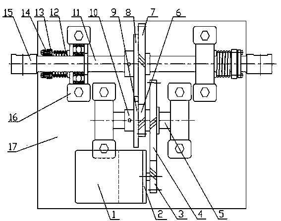
[0018] The structure of the transmission locking mechanism of the falling target involved in this embodiment is as follows: figure 1 As shown, the transmission locking mechanism for lifting and falling targets consists of motor 1, motor frame 2, gear I3, gear II4, intermediate shaft 5, incomplete gear III6, gear IV7, sheave I8, sheave II9, bushing 10, Main shaft 11, torsion spring 12, spring collar 13, expansion sleeve 14, target pole sleeve 15, bearing unit 16 and base 17 are formed.

[0019] The motor 1 is a DC brushless permanent magnet low-speed synchronous motor, which is small in size and high in torque, can be rotated frequently, has high motor efficiency, and has obvious power-saving effects.

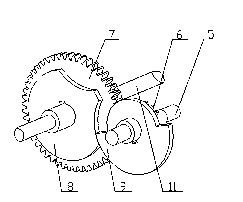
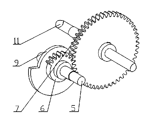
[0020] The incomplete gear III6, gear IV7, sheave I8 and sheave II9 form an incomplete gear-sheave combined mechanism, and its installation position is as follows: figure 2 with image 3 shown.

[0021] When designing the incomplete gear-groove combined mechanism, it needs t...


PUM


Abstract

The invention provides a transmission locking mechanism of an automatic target. The transmission locking mechanism of the automatic target comprises a motor (1), a motor machine frame (2), a gear I (3),a gear II (4), a middle shaft (5), an incomplete gear III (6), a gear IV (7), a sheave I (8), a sheave II (9), a shaft sleeve (10), a main shaft (11), torsion springs (12), a spring clamp ring (13),a coupling (14), a target rod sleeve (15), bearing units (16) and a base (17). The motor (1) is fixed to the base (17) through the motor machine frame (2). An output shaft of the motor is in key jointwith the gear I (3).The incomplete gear III (6), the gear IV (7), the sheave I (8) and the sheave II (9) constitute an incomplete gear-sheave combined mechanism. The transmission locking mechanism ofthe automatic target has the advantages of being accurate in transmission, high in efficiency, stable in movement, simple in overall structure and easy to carry. The transmission locking mechanism canbe applied to the automatic target in military training.

Description

technical field [0001] The invention belongs to the technical field of shooting training equipment, in particular to a transmission locking mechanism for lifting and falling targets. Background technique [0002] In the daily military live ammunition shooting training, whether the up and down target can work normally has a strong impact on the quality of the training. Generally, during training, the lifting and falling target should realize the fast lifting and locking action, and ensure a certain lifting angle, so as to detect the bullet hit information in time and start the next shooting, which requires the transmission mechanism to quickly and accurately control the falling Target rotation. [0003] Many existing lifting and falling mechanisms cannot meet the target requirements well. For example, there are many problems in the common lifting and falling targets that use the linkage mechanism as the transmission mechanism. The first is poor stability. Generally, the link...

Claims


Application Information

Patent Timeline
Patent Type & Authority Applications(China)
IPC IPC(8): F41J9/02
Inventor 柏林刘小峰刘鹏
Owner CHONGQING UNIV
Features
  • R&D
  • Intellectual Property
  • Life Sciences
  • Materials
  • Tech Scout
  • Unparalleled Data Quality
  • Higher Quality Content
  • 60% Fewer Hallucinations
Learn More