Wire bending device

Inactive Publication Date: 2005-04-14
ATELIERS DE CONSTR MECANIQUES LATOUR & FILS
View PDF6 Cites 20 Cited by
  • Summary
  • Abstract
  • Description
  • Claims
  • Application Information

AI Technical Summary

Benefits of technology

[0017] This invention aims at coping with this drawback by providing a bending device opera

Problems solved by technology

Nevertheless, for large series, one quickly finds out that they are slow, because of the retraction ti

Method used


Image

  • Wire bending device
  • Wire bending device
  • Wire bending device

Examples


Example

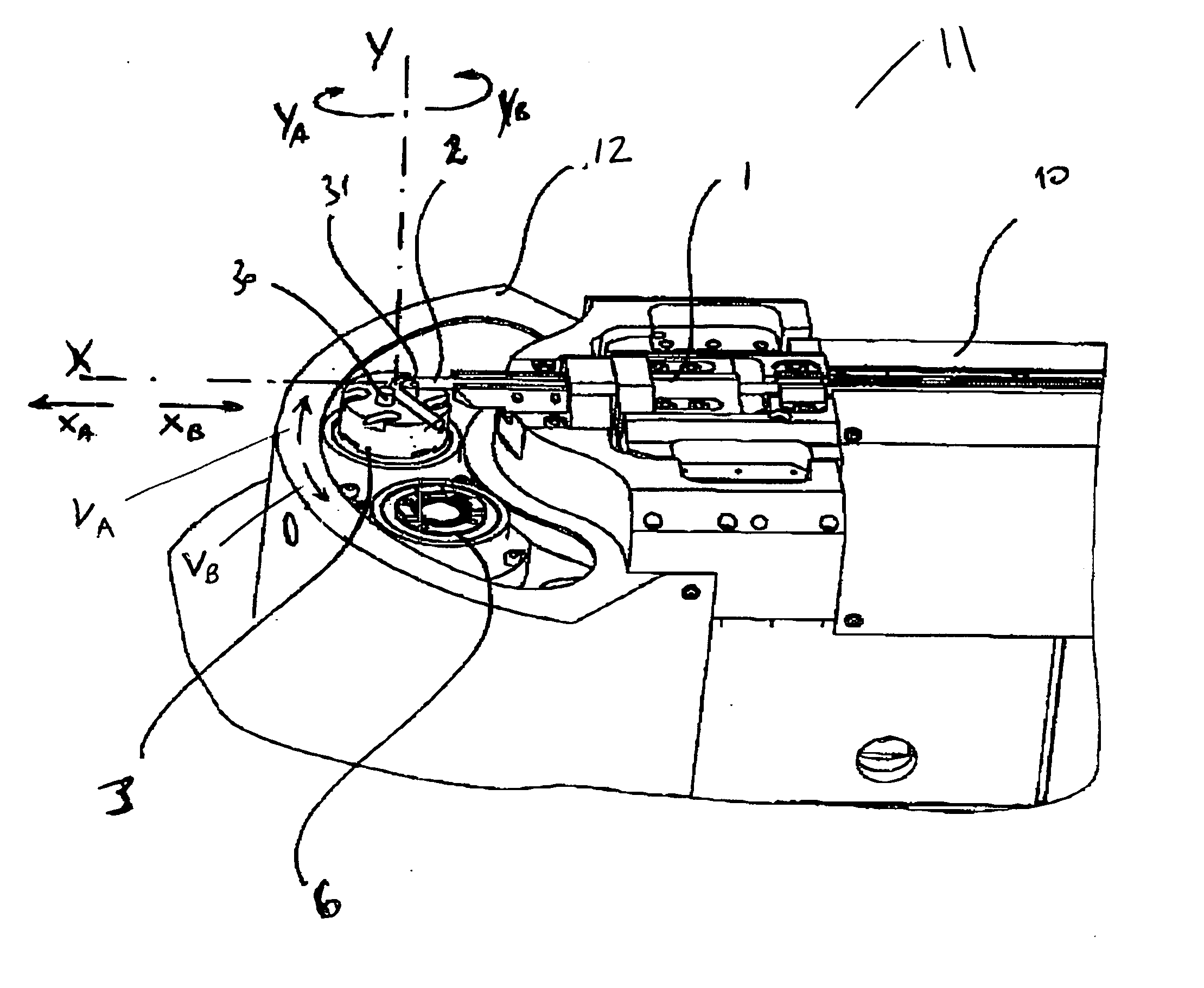
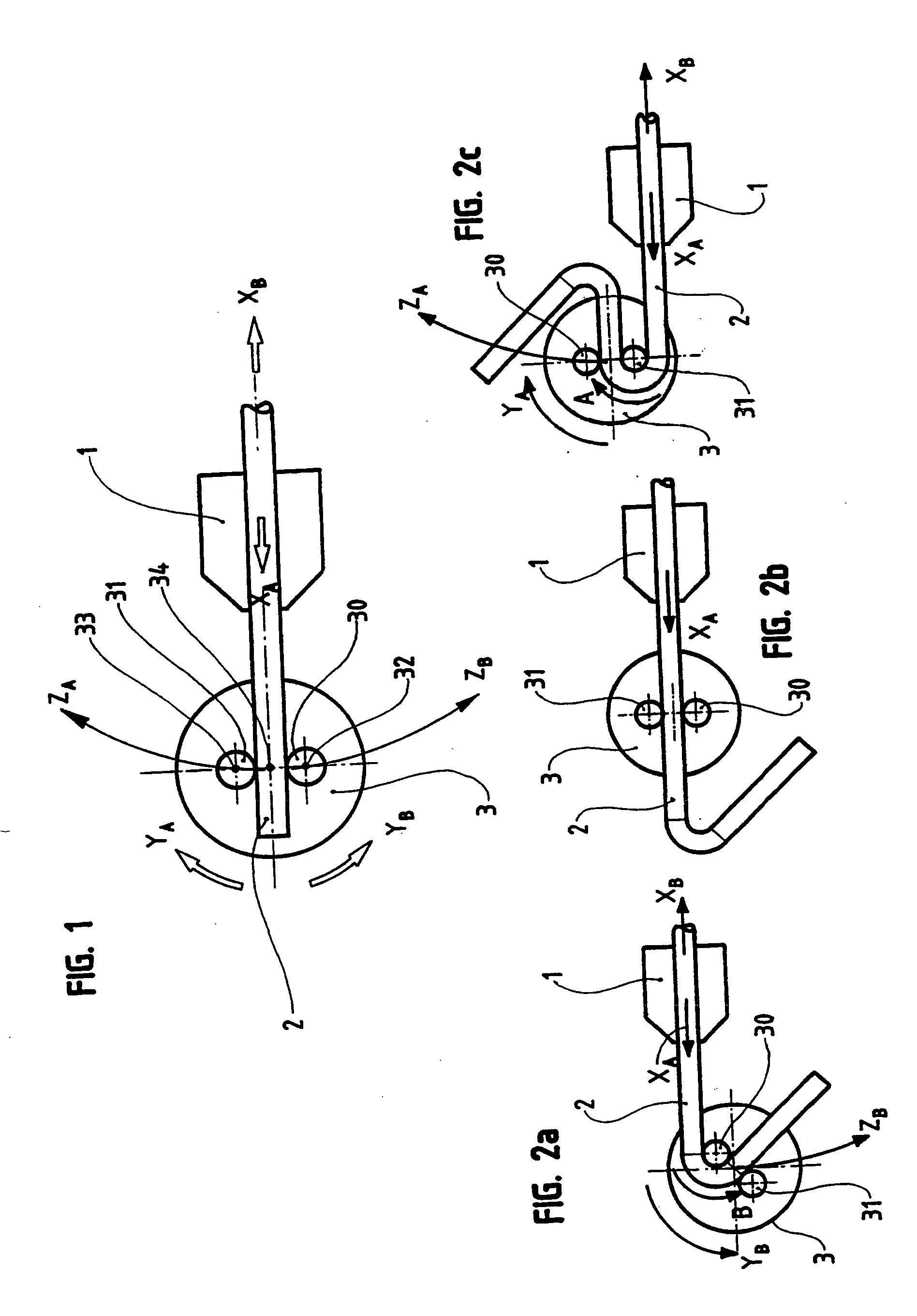
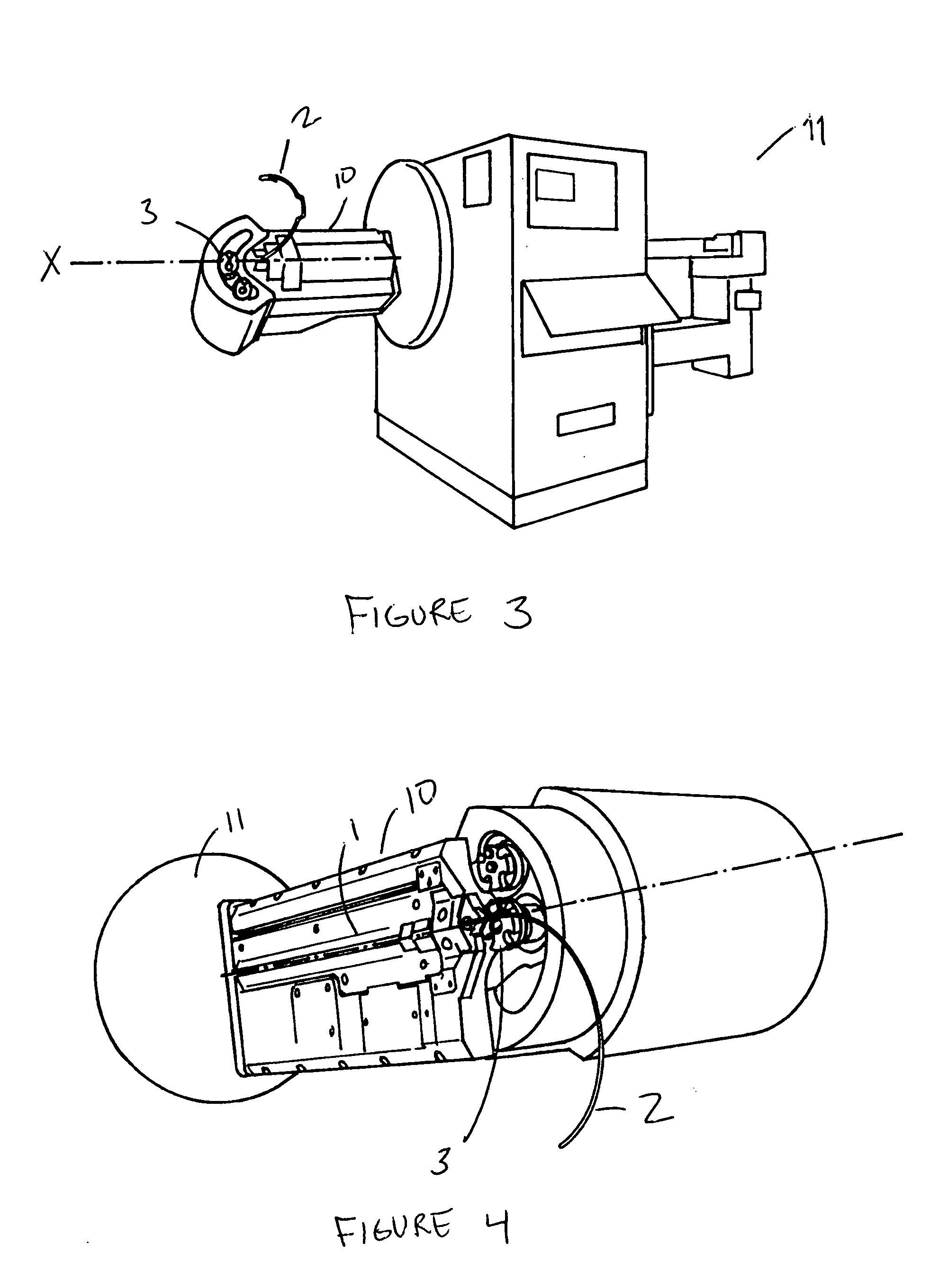
[0034] Referring to FIG. 1, one can see a partial schematic view of a bending device according to the invention, which comprises feeding means 1 for a wire 2 to be bent and a bending head 3.

[0035] The feeding means 1 is capable, through the action of the driving means, not shown, to pull the wire 2 axially, in the direction of the bending head 3, arrow XA, or in the opposite direction, arrow XB.

[0036] The bending head 3 comprises two bending tools, in this case two rollers 30 and 31, mounted and freely pivotable on the shafts 32 and 33, respectively. The wire 2 passes between the two bending tools 30 and 31 to be bent.

[0037] The bending head 3 is mobile in rotation around an axis 34, parallel to the shafts 32 and 33 and, in this particular embodiment, located in the middle of the segment that connects the latter, this rotation being able to be performed clockwise, arrow YA, or counterclockwise, arrow YB.

[0038] In addition, the bending head 3 is mobile in rotation with respect to...


PUM

PropertyMeasurementUnit
Displacementaaaaaaaaaa

Abstract

A wire bending device includes a bending head bearing two bending tools between which the wire to be bent is passed. Either tool is alternately capable of being fixed or being a pivot for rotation of the bending head therearound. The device also includes a mechanical device for feeding the wire axially in one direction or another; a mechanical device for rotatably driving the bending tools, in two different directions, about an axis of either bending tool; and a mechanical device for shifting the bending tools in a plane perpendicular to the axis about which the bending tools can rotate. There can be calculating controller for managing simultaneously the operation of the mechanical devices, so that the movements generated by the wire and bending tools are superposed.

Description

RELATED U.S. APPLICATIONS [0001] The present application is a continuation-in-part of U.S. patent application Ser. No. 10 / 203,991 filed on Aug. 15, 2002, and entitled “WIRE BENDING DEVICE”, presently pending.STATEMENT REGARDING FEDERALLY SPONSORED RESEARCH OR DEVELOPMENT [0002] Not applicable. REFERENCE TO MICROFICHE APPENDIX [0003] Not applicable. FIELD OF THE INVENTION [0004] The present invention relates to a wire bending device. BACKGROUND OF THE INVENTION [0005] There are presently two large categories of wire bending machines: those used for large series that comprise bending tools placed in a position corresponding to the profile to be imparted to the metal wire; and those used for small series that permit passing from one profile to another, without it being necessary to change tools, in contrast to the preceding large series machines. [0006] All the machines of this second category make use of the same bending method, consisting of passing the wire between two bending tools...

Claims


Application Information

Patent Timeline
IPC IPC(8): B21D7/022B21D11/12B21F1/00
CPCB21D7/022B21F1/006B21F1/00B21D11/12
Inventor LATOUR, YVES
Owner ATELIERS DE CONSTR MECANIQUES LATOUR & FILS
Why Eureka
Try Eureka