Automatic quenching oil cooling system

A technology of automatic cooling and quenching oil, applied in the direction of quenching agent, quenching device, heat treatment equipment, etc., can solve the problems of reducing cooling effect, inconsistent temperature of quenching liquid, affecting quenching effect, etc., to ensure the effect of cooling effect and quenching quality.

Inactive Publication Date: 2019-01-15
湖北博英精工科技股份有限公司
View PDF0 Cites 2 Cited by
  • Summary
  • Abstract
  • Description
  • Claims
  • Application Information

AI Technical Summary

Problems solved by technology

[0003] During the quenching process, since the quenching liquid will absorb a large amount of heat from the workpiece, the temperature of the quenching liquid will rise sharply after quenching for a certain period of time, seriously affecting the quenching effect
In order to solve this phenomenon, the traditional cooling method is mainly to install cooling pipes in the quenching liquid, and the cooling pipes are filled with circulating cooling liquid to reduce the temperature of the quenching liquid. The main defects of this cooling method are: if you want to get better In order to improve the cooling effect, denser cooling pipes need to be arranged in the quenching liquid. In this way, the densely arranged cooling pipes will occupy a large volume of the quenching liquid box and reduce the quenching efficiency of the workpiece; but if in order to ensure sufficient quenching space, It is necessary to reduce the number of cooling pipes, which will reduce the cooling effect;
[0004] In addition, during the quenching process, the heated workpiece is often sent into the upper or lower layer of the quenching liquid, resulting in inconsistent temperature of the upper or lower layer of quenching liquid, which seriously affects the quenching quality of the workpiece

Method used


Image

  • Automatic quenching oil cooling system
  • Automatic quenching oil cooling system
  • Automatic quenching oil cooling system

Examples


Embodiment Construction

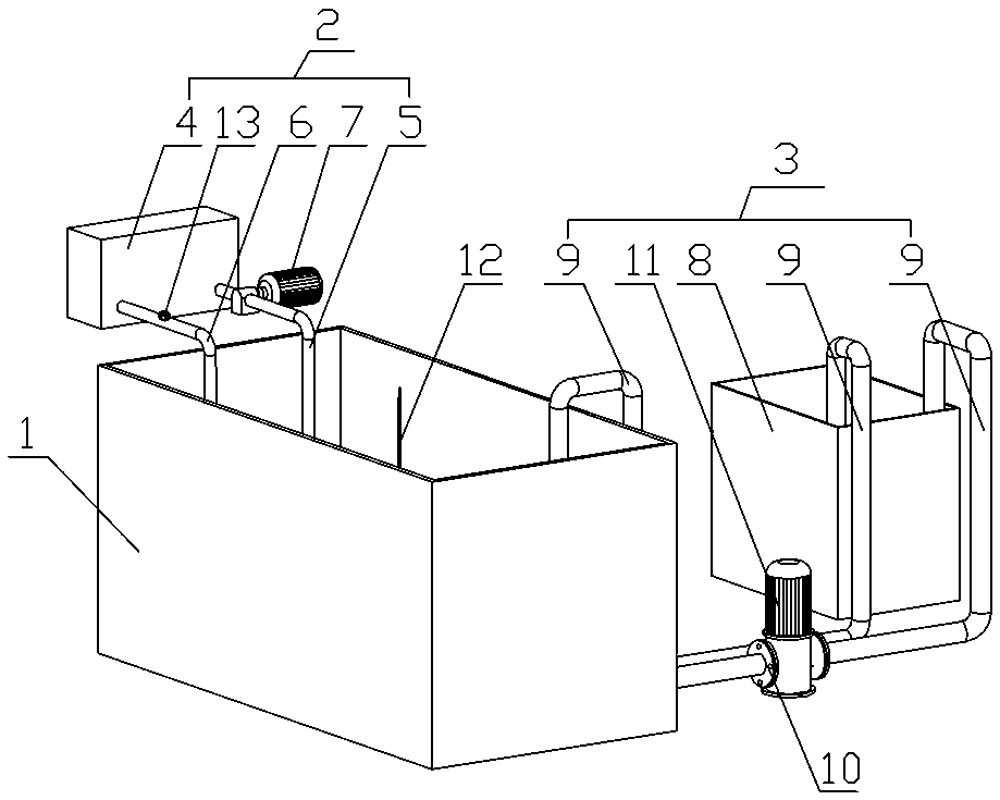
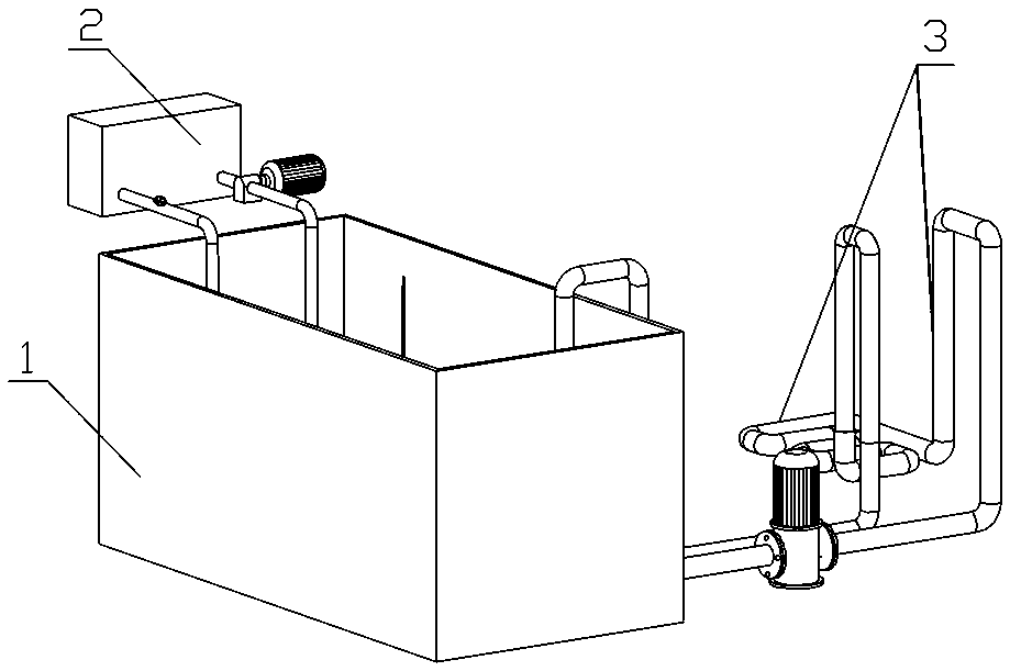
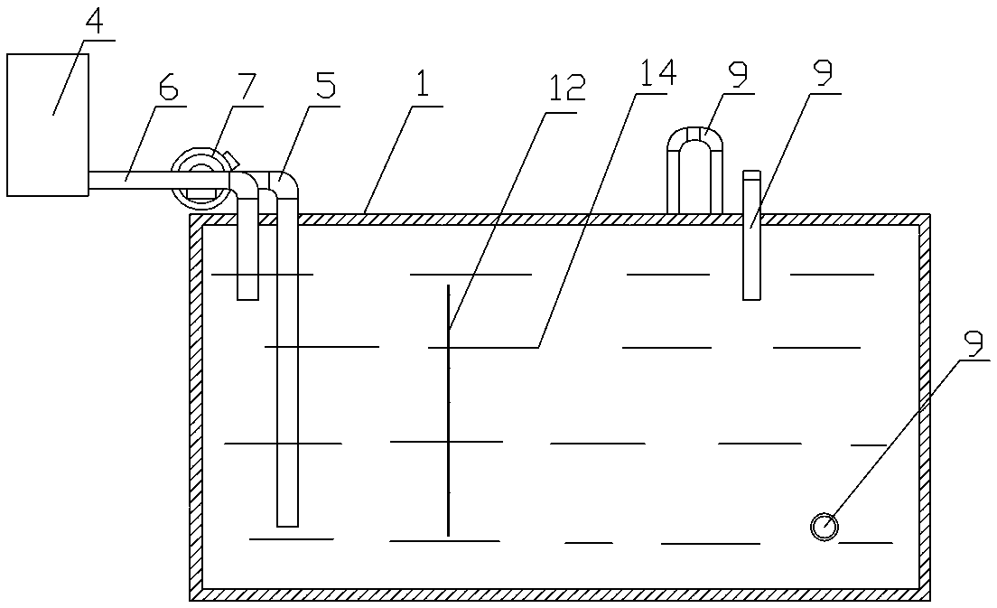
[0017] In this embodiment, an automatic cooling system for quenching oil has an oil storage tank 1 with an open upper end, and the oil storage tank 1 is connected with an internal cooling circulation device 2 and an external cooling circulation device 3, and the internal cooling circulation device 2 has Temporary oil storage tank 4, between the temporary oil storage tank 4 and the oil storage tank 1 is respectively connected with a liquid suction pipe A5 and a liquid outlet pipe A6, the liquid inlet of the liquid suction pipe A5 is close to the bottom of the oil storage tank 1, at the bottom of the liquid suction pipe A suction pump A7 is also installed on the pipe body of A5, and the liquid outlet of the liquid outlet pipe A6 is located at the upper part of the oil storage tank 1. In addition, a valve 13 for controlling the flow rate of the circulating quenching oil 14 is also installed on the pipe body of the liquid outlet pipe A. .

[0018] In this embodiment, the external ...


PUM


Abstract

The invention relates to the field of workpiece quenching processes, in particular to an automatic quenching oil cooling system which is provided with an oil storage tank with an opening in the upperend. The oil storage tank is connected with a cooling circulation device in the tank and a cooling circulation device outside the tank; the cooling circulation device in the tank is provided with a temporary oil storage tank; a pumping pipe A and a discharging pipe A communicate between the temporary oil storage tank and the oil storage tank; a pumping pump A is arranged on a pipe body of the pumping pipe A; the cooling circulation device outside the tank is provided with a cooling water tank and a pumping pipe B; a pipe body of the pumping pipe B is located on the outer part of the oil storage tank; a part of pipe body stretches into the cooling water tank; and a pumping pump B is arranged on the pumping pipe B. According to the automatic quenching oil cooling system provided by the invention, an active cooling mode is adopted, and heated quenching liquid is actively pumped into the cooling water tank, so that a cooling effect is ensured, the problem that a traditional cooling pipeline occupies the volume in the oil storage tank is avoided, and the automatic quenching oil cooling system has a favorable application prospect.

Description

technical field [0001] The invention relates to the field of workpiece quenching technology, in particular to an automatic quenching oil cooling system. Background technique [0002] Quenching is an important heat treatment process in industrial production and a key technology to improve the physical properties of the workpiece. In the general process, the heated workpiece is placed in a special quenching liquid to rapidly cool the workpiece to improve certain physical properties (including rigidity , hardness, wear resistance, fatigue strength and toughness, etc.). [0003] During the quenching process, since the quenching liquid will absorb a large amount of heat from the workpiece, the temperature of the quenching liquid will rise sharply after quenching for a certain period of time, seriously affecting the quenching effect. In order to solve this phenomenon, the traditional cooling method is mainly to install cooling pipes in the quenching liquid, and the cooling pipes ...

Claims


Application Information

Patent Timeline
IPC IPC(8): C21D1/64C21D1/58
CPCC21D1/64C21D1/58
Inventor 陈绪浩陈学中
Owner 湖北博英精工科技股份有限公司
Why Eureka
Try Eureka