Method and device for compressing air

A technology of compressing air and compressing cylinders, applied in mechanical equipment, liquid variable capacity machinery, variable capacity pump components, etc., can solve the problems of grid shock, the impact of motor life is also great, the motor load is large, etc., to improve efficiency , Improve the service life, the effect of simple mechanism

Inactive Publication Date: 2019-01-15
斯丹红
View PDF0 Cites 0 Cited by
  • Summary
  • Abstract
  • Description
  • Claims
  • Application Information

AI Technical Summary

Problems solved by technology

[0002] Since the appearance of air compressors, the utilization of air power by human beings has been greatly increased, but most of the air compressors on the market today have a problem, that is, when the air compressor is just started, the load on the motor is the largest, which has a very large impact on the power grid. It also has a great impact on the life of the motor, so it needs to be improved

Method used


Image

  • Method and device for compressing air
  • Method and device for compressing air
  • Method and device for compressing air

Examples


Embodiment Construction

[0021] All the features disclosed in this specification, or all disclosed methods or steps in the process, except for mutually exclusive features and / or steps, can be combined in any manner.

[0022] Any feature disclosed in this specification (including any appended claims, abstract and drawings), unless specifically stated, can be replaced by other equivalent or alternative features with similar purposes. That is, unless otherwise stated, each feature is just one example of a series of equivalent or similar features.

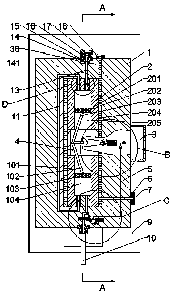
[0023] Such as Figure 1-5 As shown, a method and equipment for compressing air of the device of the present invention includes a gas compression device 1 and a first-stage compression cylinder 2 arranged in the gas compression device 1 and opening downwards and surrounding the first-stage compression In the cooling water cavity 204 around the cylinder 2, a cooling water nozzle 6 is fixed on the right side of the gas compression device 1, and the cooling water cav...


PUM


Abstract

The invention discloses a method and device for compressing air. The device comprises a gas compression device, a primary compression cylinder being disposed in the gas compression device and having adownward opening, and a cooling water chamber surrounding the primary compression cylinder. A cooling water nozzle is fixedly disposed on a right side of the gas compression device. The cooling waterchamber is in communication with the cooling water nozzle. An air inlet valve is disposed in an upper wall of the primary compression cylinder. An air intake duct is disposed in the air inlet valve.An air inlet valve flap having a downward opening is disposed slidably in the air intake duct. The air inlet valve flap is fixedly connected with the air intake duct by an air intake compression spring. An exhaust valve located at a left side of the air inlet valve is arranged in the upper wall of the primary compression cylinder. The exhaust valve is provided internally with an exhaust passage ina penetrating manner. The exhaust valve is provided internally with an exhaust valve flap slidably connected with the exhaust passage and having an upward opening. The exhaust valve flap is fixedly connected with the exhaust passage by an exhaust compression spring.

Description

Technical field [0001] The invention relates to the field of industrial technology, in particular to a method and equipment for compressing air. Background technique [0002] Since the advent of air compressors, the use of aerodynamic power by humans has been greatly increased. However, most of the air compressors on the market today have a problem. When the air compressor is just started, the load of the motor is the largest, which has a great impact on the power grid. It also has a great impact on the life of the motor, so it needs to be improved. Summary of the invention [0003] In view of the above technical deficiencies, the present invention provides a method and equipment for compressing air. [0004] The present invention is a method and equipment for compressing air, including a gas compression device, a first-stage compression cylinder arranged in the gas compression device and opened downward, and a cooling water cavity surrounding the first-stage compression cylinder, ...

Claims


Application Information

Patent Timeline
Patent Type & Authority Applications(China)
IPC IPC(8): F04B27/02F04B35/00F04B35/04F04B37/12F04B39/00F04B39/02F04B39/10F04B39/16F04B39/12
CPCF04B27/02F04B35/00F04B35/04F04B37/12F04B39/00F04B39/0284F04B39/10F04B39/12F04B39/16
Inventor 斯丹红
Owner 斯丹红
Why Eureka
Try Eureka