Series voltage compensator and system for suppressing commutation failure of conventional DC converter station

A series voltage, commutation failure technology, applied in the direction of AC power input conversion to AC power output, electrical components, power transmission AC network, etc., can solve the problem of insufficient resistance to commutation failure, low utilization rate of additional devices, thyristor voltage High stress and other problems, to achieve the effect of improving the ability to prevent commutation failure, good engineering practicability, and low cost

Active Publication Date: 2020-10-13
TSINGHUA UNIV +1
View PDF3 Cites 0 Cited by
  • Summary
  • Abstract
  • Description
  • Claims
  • Application Information

AI Technical Summary

Problems solved by technology

However, due to the need to install additional circuits in each bridge arm of the LCC converter, the utilization rate of the additional components is not high, and it involves the modification of the LCC converter body, which is costly and difficult
[0006] In addition, there are also researches, such as a new type of capacitor-commutated converter based on the anti-parallel thyristor full-bridge sub-module, further based on the full-bridge module composed of bidirectional thyristors connected to the AC end of the LCC converter, and a ECCC (Enhanced CCC, The topology of the enhanced capacitor commutated converter can save 50% of the module capacitor capacity compared with the additional circuit scheme in the bridge arm, and at the same time avoid the transformation of the bridge arm of the converter. Significantly insufficient resistance to commutation failure of the first and second commutation processes after a voltage failure and high voltage stress on the thyristors in the module

Method used


Image

  • Series voltage compensator and system for suppressing commutation failure of conventional DC converter station
  • Series voltage compensator and system for suppressing commutation failure of conventional DC converter station
  • Series voltage compensator and system for suppressing commutation failure of conventional DC converter station

Examples


Embodiment Construction

[0039] Embodiments of the present invention are described in detail below, examples of which are shown in the drawings, wherein the same or similar reference numerals designate the same or similar elements or elements having the same or similar functions throughout. The embodiments described below by referring to the figures are exemplary and are intended to explain the present invention and should not be construed as limiting the present invention.

[0040] The series voltage compensator and system for suppressing commutation failure of conventional DC converter stations according to the embodiments of the present invention will be described below with reference to the accompanying drawings. Failed series voltage compensator.

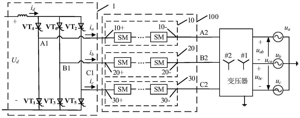
[0041] figure 1 It is a structural schematic diagram of a series voltage compensator for suppressing commutation failure of a conventional DC converter station according to an embodiment of the present invention.

[0042] Such as figure 1 As shown, ...


PUM


Abstract

The invention discloses a series voltage compensator and system for suppressing commutation failure of a conventional DC converter station. The compensator includes: first to third converter chains, each of the first to third converter chains It includes multiple fully-controlled voltage source sub-modules, which are connected in series between the LCC-HVDC converter transformer and the AC port of the converter to control the series voltage to assist valve group commutation, and increase the power of the LCC-HVDC converter commutation voltage area. The compensator uses a converter chain composed of controllable full-bridge sub-modules to be connected in series between the AC port of the conventional DC system converter and the converter transformer, and does not need to modify the internal structure of the original converter bridge arm. It has good ability to suppress commutation failure and accelerate recovery after failure, which can significantly improve the ability of LCC‑HVDC to defend against commutation failure and the recovery speed after commutation failure. It has high control flexibility, low cost, and good engineering practicality.

Description

technical field [0001] The invention relates to the technical field of high-voltage direct current transmission, in particular to a series voltage compensator and a system for suppressing commutation failure of a conventional direct current converter station. Background technique [0002] The traditional grid-commutated high-voltage direct current transmission system (line commutated converter, LCC-HVDC) has the advantages of long-distance large-capacity power transmission and controllable active power, and is widely used around the world. However, since the thyristors used in its converters need to rely on the AC system to provide commutation voltage, commutation failures are prone to occur in the event of AC system failure, resulting in a surge in DC current and a rapid loss of DC transmission power. In addition, in recent years, some regional power grids in my country have had multiple DC feed-ins. Once a commutation failure occurs in a certain DC line, the coupling of th...

Claims


Application Information

Patent Timeline
Patent Type & Authority Patents(China)
IPC IPC(8): H02J3/36H02M5/458
CPCH02J3/36H02M5/458H02M1/0067Y02E60/60
Inventor 侯灵犀魏应冬张树卿李笑倩赵彪姜齐荣宗炫君邹盛
Owner TSINGHUA UNIV
Why Eureka
Try Eureka