Orthopedic dressing changing rack

A dressing rack and orthopedic technology, applied in the field of medical equipment, can solve problems such as the inability to rotate and adjust the position

Pending Publication Date: 2019-01-18
徐菁涵
View PDF0 Cites 0 Cited by
  • Summary
  • Abstract
  • Description
  • Claims
  • Application Information

AI Technical Summary

Problems solved by technology

This orthopedic dressing change rack has no base and cannot be rotated around the base to adjust its position

Method used


Image

  • Orthopedic dressing changing rack
  • Orthopedic dressing changing rack
  • Orthopedic dressing changing rack

Examples


Embodiment Construction

[0024] The following will clearly and completely describe the technical solutions in the embodiments of the present invention with reference to the accompanying drawings in the embodiments of the present invention. Obviously, the described embodiments are only some of the embodiments of the present invention, not all of them. Based on the embodiments of the present invention, all other embodiments obtained by persons of ordinary skill in the art without making creative efforts belong to the protection scope of the present invention.

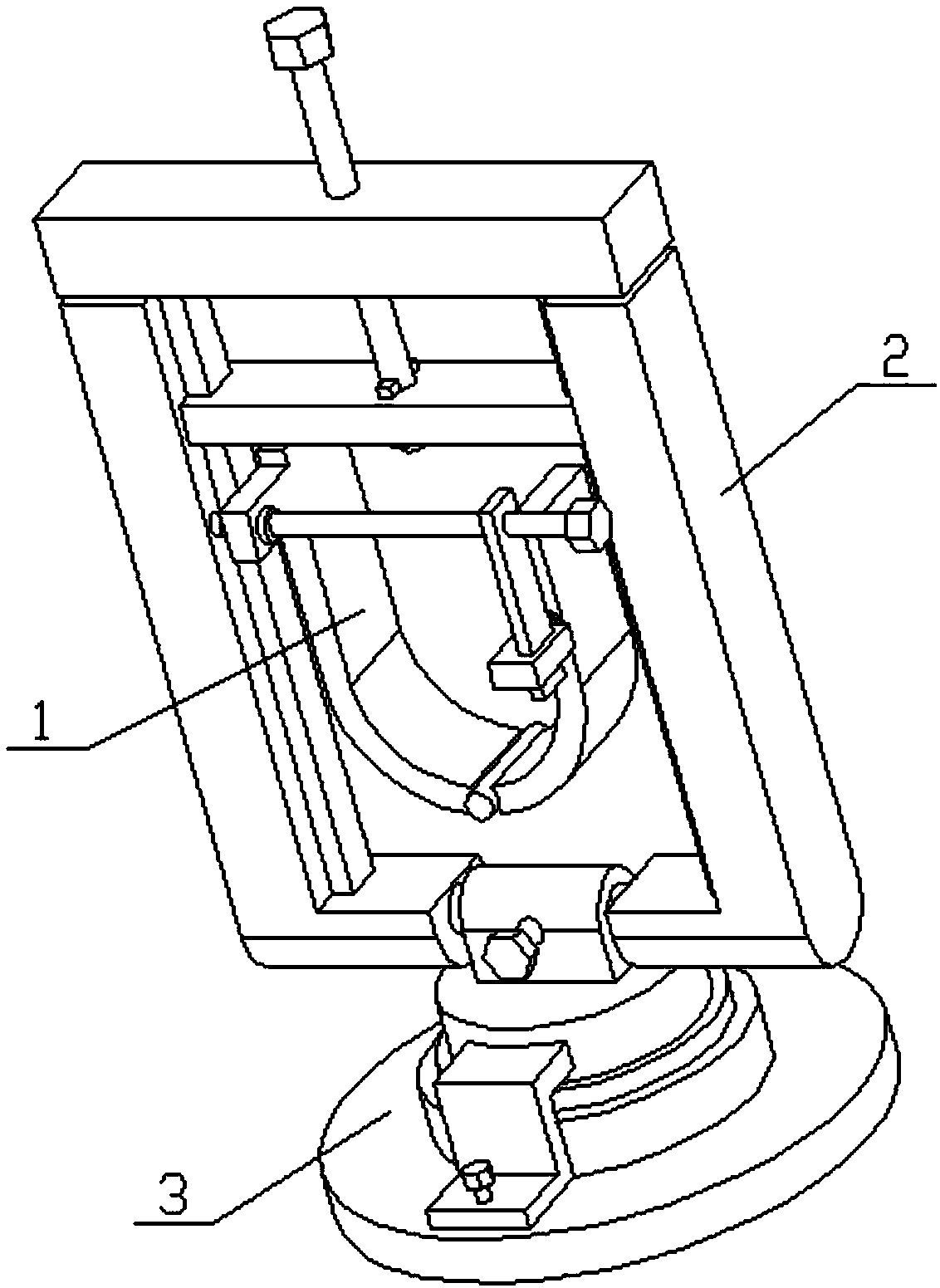
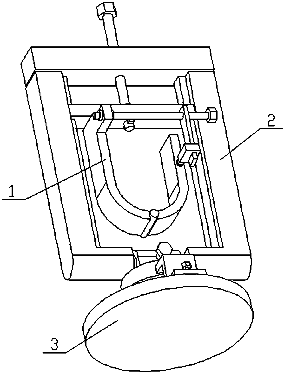
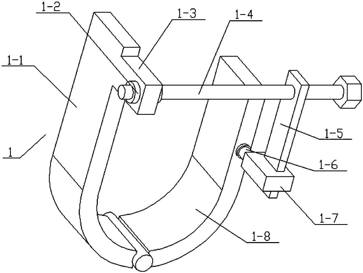
[0025] see Figure 1-7 , the invention provides a technical solution: an orthopedic dressing rack, including a bracket assembly 1 and a frame assembly 2, the bracket assembly 1 includes a left half U-shaped frame 1-1, a circular block 1-2, Cam 1-3, adjusting screw 1-4, vertical insert plate 1-5, rotating shaft 1-6, socket 1-7 and right half U-shaped frame 1-8, described left half U-shaped frame 1-1 and The lower end of the right half U-shaped fr...


PUM


Abstract

The invention discloses an orthopedic dressing changing rack, including a bracket assembly and a frame assembly. The bracket assembly includes a left half U-shaped bracket, a circular stopper, a tab,an adjusting screw, a vertical insertion plate, a socket and a right half U-frame. The lower end of the left half U-shaped frame and the right half U-shaped frame are hingedly connected, the front endof the upper end of the left half U-shaped frame is fixedly connected with the convex plate, the left end clearance of the adjusting screw is fitted and inserted on the convex plate, the left end ofthe adjusting screw is fixedly connected with two circular stoppers, two circular stoppers are sandwiched between the left and right ends of the convex plates, The rear end of the socket is fixedly connected with the rotating shaft, the rotating shaft is rotatably connected with the front end of the right half U-shaped frame through bearings, the upper end of the vertical insertion plate is threadably connected with the right end of the adjusting screw, and the lower end of the vertical insertion plate is slidably connected with the socket.

Description

technical field [0001] The invention relates to a medical device, in particular to an orthopedic dressing rack. Background technique [0002] A current orthopedic dressing rack includes a support frame and a bracket. The bracket includes a connecting block. Both ends of the connecting block are equipped with receiving parts through fixing nuts. The two sides of the bottom of the receiving part are respectively equipped with a sling one and a sling three. The bottom of sling 1 is connected to sling 2 through an adjustment buckle, and the bottom ends of sling 2 and sling 3 are both connected to receiving brackets through pendants. The inner side of the receiving brackets is provided with a receiving screen, and the bottom of the receiving screen is provided with a partition. Cavity, the left end of the compartment is provided with a drain port, and the right end of the bracket is movably installed with a joint bracket. The present invention makes the bracket of the orthopedic...

Claims


Application Information

Patent Timeline
Patent Type & Authority Applications(China)
IPC IPC(8): A61G12/00
CPCA61G12/00
Inventor 徐菁涵
Owner 徐菁涵
Why Eureka
Try Eureka