Efficient circulation type rubber crushing machine

A circulatory, pulverizer technology, applied in solid separation, sieves, grilles, etc., can solve the problems of incomplete rubber pulverization and dead corners at the bottom of the machine body, and achieve the effect of being conducive to repeated pulverization, improving quality and novel ideas.

Active Publication Date: 2019-01-18
漯河市利道液压科技有限公司
View PDF5 Cites 10 Cited by
  • Summary
  • Abstract
  • Description
  • Claims
  • Application Information

AI Technical Summary

Problems solved by technology

[0003] In view of the above situation, in order to solve the problems existing in the prior art, the purpose of the present invention is to provide a high-efficiency circulating rubber pulverizer, which can effectively solve the problem of dead corners at the bottom of the machine body and incomplete rubber pulverization

Method used


Image

  • Efficient circulation type rubber crushing machine
  • Efficient circulation type rubber crushing machine
  • Efficient circulation type rubber crushing machine

Examples


Embodiment Construction

[0014] The specific embodiments of the present invention will be described in further detail below with reference to the accompanying drawings.

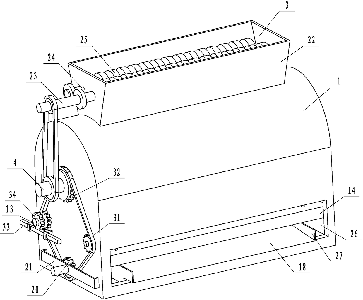
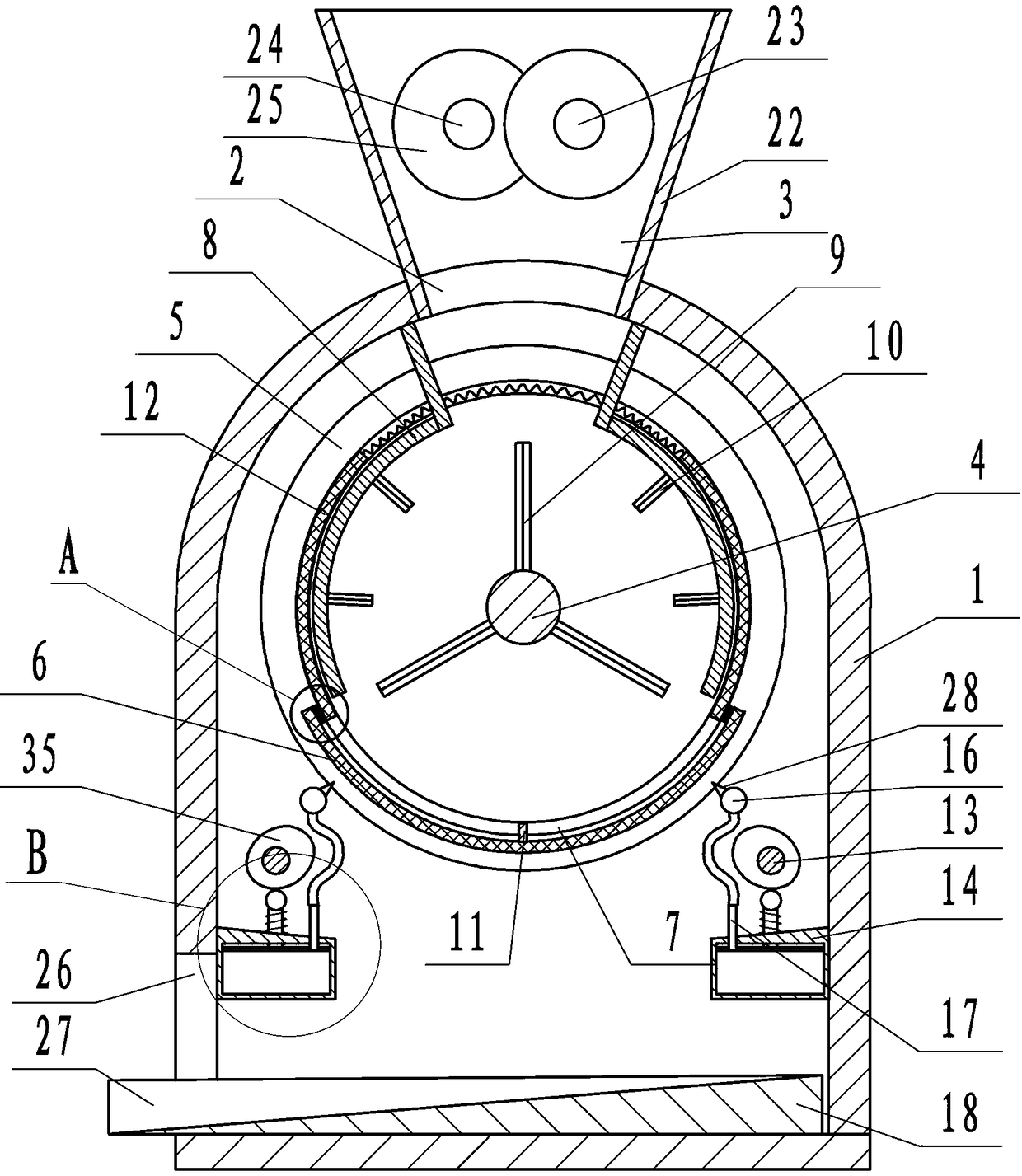
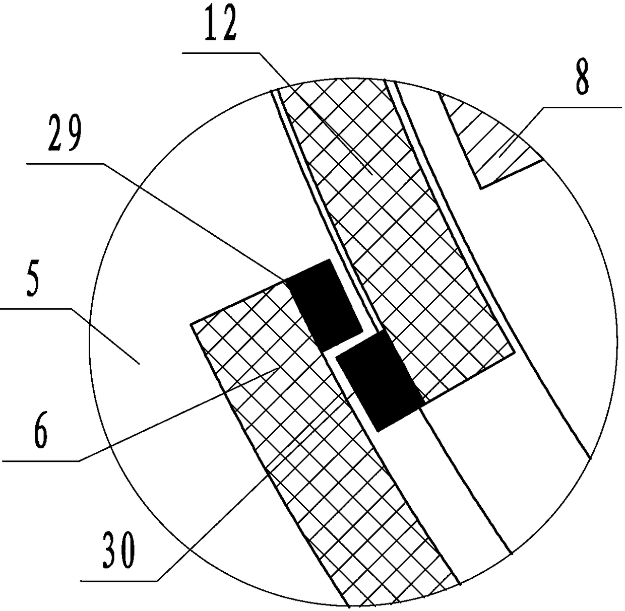
[0015] by Figure 1 to Figure 7 Given that the present invention includes a horizontal machine body 1, a feed port 2 is provided above the body 1, a tearing crusher 3 is installed on the body 1, and the discharge of the crusher 3 corresponds to the feed port 2 of the body 1 ; The body 1 penetrates the first rotating shaft 4 placed in the front and rear directions, the front and rear ends of the first rotating shaft 4 are sleeved with a disc 5 that can rotate relative to the first rotating shaft 4, and the two front and rear discs 5 are fixedly installed An arc-shaped first filter screen 6; the inner side wall of the first filter screen 6 is equipped with vertical baffles 11 placed in the front-to-back direction; the inner edge surfaces of the two front and rear discs 5 are provided with annular grooves 7, two front and rear Two arc-sha...


PUM


Abstract

The invention relates to an efficient circulation type rubber crushing machine, which effectively solves the problems that dead corners exist at the bottom of a machine body; the rubber crushing is not thorough. In order to solve the problems, the efficient circulation type rubber crushing machine has the technical scheme that the efficient circulation type rubber crushing machine comprises a horizontal machine body, wherein a tearing type crushing machine is arranged on the machine body; a first rotating shaft is arranged in the machine body in a penetrating way; a front circular disc and a back circular disc are arranged on the first rotating shaft; a first filter screen is arranged between the circular discs; a baffle plate is arranged at the bottom of the first filter screen; a secondfilter screen capable of sliding relative to the inner edge surface of the first filter screen is arranged on the inner edge surface of the first filter screen; two arc-shaped plates used for blockingmaterials are arranged in the machine body; crushing cutters are arranged between the first rotating shaft and the arc-shaped plate; a second rotating shaft is arranged in the box body; a box body isarranged under the second rotating shaft; an extruding plate is arranged in the box body; the second rotating shaft rotates to drive the driving plate to vertically move, so that the gas in the box body upwards blows; a material conveying plate is arranged under the machine body; the material conveying plate is matched with a first chain wheel through a lead screw; the first chain wheel rotates to drive the lead screw and the material conveying plate to do forward and backward movement. The efficient circulation type rubber crushing machine provided by the invention has the advantages that the use is convenient; the crushing effect is good.

Description

Technical field [0001] The invention relates to the field of rubber production and processing, in particular to a high-efficiency circulating rubber crusher. Background technique [0002] At present, the horizontal crusher includes a crusher body. The crusher body is equipped with a rotating shaft, a crushing blade and a motor; the crushing blade is arranged on the rotating shaft; the motor drives the rotating shaft to rotate, and the rotating shaft drives the crushing blade on it to rotate, thereby achieving the purpose of crushing ; But the crusher with the above structure still has many problems for crushing rubber. For example, after the rubber is blown away, it generally rotates along the side wall of the machine body, and the crushing blade cannot be too close to the body wall, so it surrounds Larger rubber particles on the side walls of the machine body cannot be crushed sufficiently, especially at the bottom of the machine body, which will cause serious rubber particle ho...

Claims


Application Information

Patent Timeline
Patent Type & Authority Applications(China)
IPC IPC(8): B02C18/14B02C23/16B02C23/24B26D1/24B07B1/52
CPCB02C18/14B02C23/16B02C23/24B07B1/522B26D1/24
Inventor 田海涛夏青王非陈亮丁春侠
Owner 漯河市利道液压科技有限公司
Why Eureka
Try Eureka