Ore dressing device with ore material thickness-adjustable function and ore dressing technology thereof
A feeding device and mineral material technology, which is applied in the directions of magnetic separation, solid separation, chemical instruments and methods, etc., can solve the problems of inability to adjust the thickness of mineral material, and cannot apply to different types of mineral materials with different specifications, so as to achieve a balance of recovery rate And beneficiation efficiency, high recovery rate, high throughput effect
- Summary
- Abstract
- Description
- Claims
- Application Information
AI Technical Summary
Problems solved by technology
Method used
Image
Examples
Embodiment 1
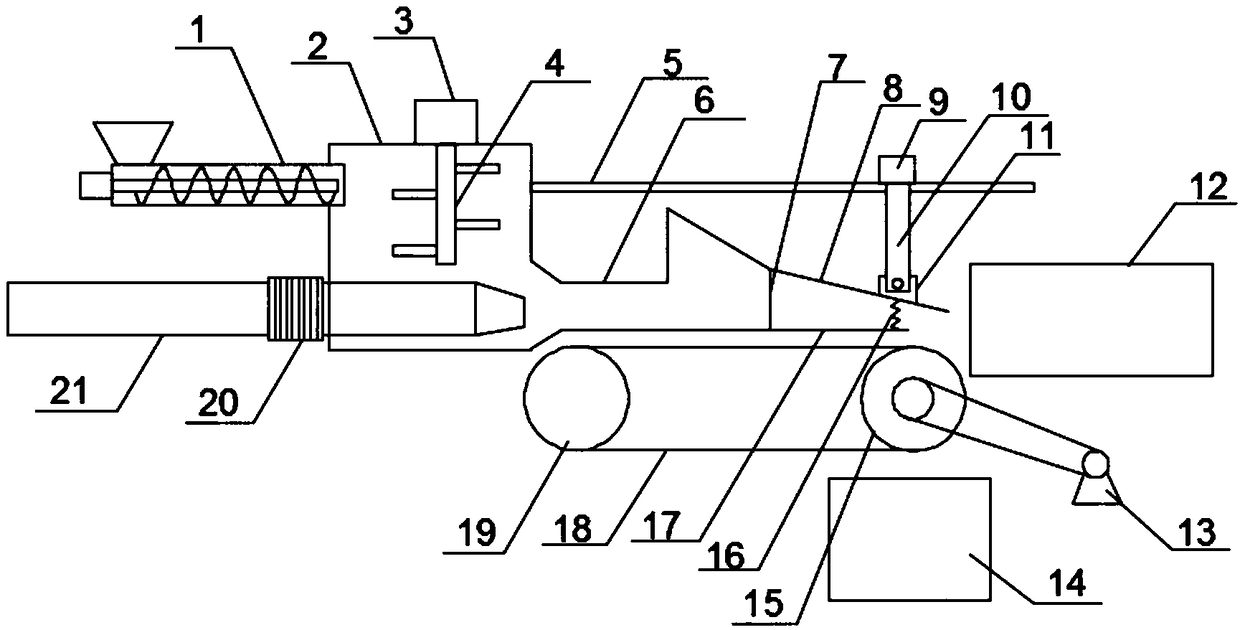
[0044] A beneficiation device with adjustable mineral material thickness, comprising an acceleration chamber 2, a feeding device 1, a spray pipe 6 and an air supply pipe 21, the feeding device 1 is connected to the upper part of the acceleration chamber 2, and the lower part of the acceleration chamber 2 is provided with a connected acceleration chamber 2 and the opening of the nozzle 6, the air outlet of the air supply pipe 21 extends horizontally into the acceleration chamber 2 and points to the opening; the end of the nozzle 6 away from the acceleration chamber 2 is provided with a flat mouth 7, and the flat mouth 7 is provided with a thickness adjustment device, the thickness adjusting device includes an upper baffle plate 8 hinged to the top of the flat mouth 7 and a lower baffle plate 17 horizontally arranged at the bottom of the flat mouth 7, and the upper baffle plate 8 and the lower baffle plate 17 are formed between the ends away from the flat mouth 7. Outlet 177; the...
Embodiment 2
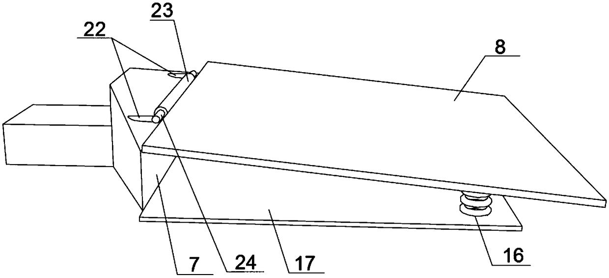
[0048] Based on Embodiment 1, a first fixed shaft 24 and a first shaft sleeve 23 that can rotate around the first fixed shaft 24 are arranged above the flat mouth 7, and the first fixed shaft 24 is connected with the nozzle pipe 6 through the first fixed rod 22, so The above-mentioned baffle plate 8 is connected with the first bushing 23 . By arranging the first fixed shaft 24 and the first bushing 23, it is ensured that when the telescopic rod 10 stretches, the upper baffle 8 can rotate up and down around the first fixed shaft 24, so that the distance between the end of the upper baffle 8 and the lower baffle 17 can be adjusted. distance between. A connection block 11 is fixed on the upper baffle plate 8, and the connection block 11 is hinged with the telescopic rod 10. A support plate 5 is connected to the side wall of the acceleration chamber 2 , and the driving motor 9 is located on the support plate 5 .
Embodiment 3
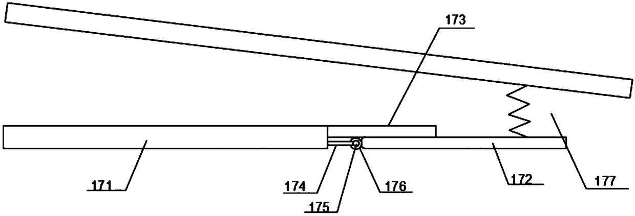
[0050] Based on Embodiment 1, the fixed plate 171 is connected to the second fixed shaft 175 through the second fixed rod 174, and the second fixed shaft 175 is covered with a second shaft sleeve 176 that can rotate around the second fixed shaft 175. The rotating plate 172 Connect with the second shaft sleeve 176 . By setting the second fixed shaft 175 and the second shaft sleeve 176, it is ensured that when the rotating plate 172 is subjected to an increased downward force, it can overcome the tension of the spring 16 and rotate downward around the second fixed shaft 175, thereby automatically solving the problem of the discharge port. 177 clogging problems.
PUM
 Abstract
Description
Claims
Application Information
 - R&D
- Intellectual Property
- Life Sciences
- Materials
- Tech Scout
- Unparalleled Data Quality
- Higher Quality Content
- 60% Fewer Hallucinations
Browse by: Latest US Patents, China's latest patents, Technical Efficacy Thesaurus, Application Domain, Technology Topic, Popular Technical Reports.
© 2025 PatSnap. All rights reserved.Legal|Privacy policy|Modern Slavery Act Transparency Statement|Sitemap|About US| Contact US: help@patsnap.com


