Flotation machine impeller for increasing width of conveying area

A flotation machine and width technology, applied in flotation, solid separation, etc., can solve problems such as inability to produce air dispersion and pulp circulation, poor recovery effect of flotation machines, and reduced probability of secondary collisions

Active Publication Date: 2019-01-18
BGRIMM MACHINERY & AUTOMATION TECH CO LTD +1
View PDF15 Cites 6 Cited by
  • Summary
  • Abstract
  • Description
  • Claims
  • Application Information

AI Technical Summary

Problems solved by technology

The series of impellers described in the above patent cannot produce effective air dispersion and slurry circulation in the cylindrical area, and the overall transport area width of the flotation machine is not large, which will cause the secondary collision probability of particles falling off the foam layer in this area. decrease, making the overall recovery effect of the flotation machine worse

Method used


Image

  • Flotation machine impeller for increasing width of conveying area
  • Flotation machine impeller for increasing width of conveying area
  • Flotation machine impeller for increasing width of conveying area

Examples


Embodiment Construction

[0016] The embodiments of the present invention will be further described in detail below. The content not described in detail in the embodiments of the present invention belongs to the prior art known to those skilled in the art.

[0017] The flotation machine impeller with wider transport area width of the present invention, its preferred embodiment is:

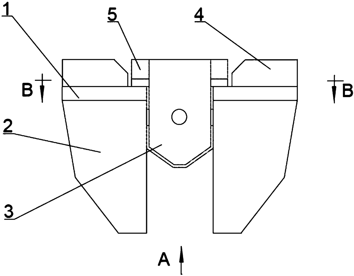
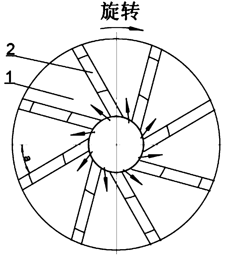
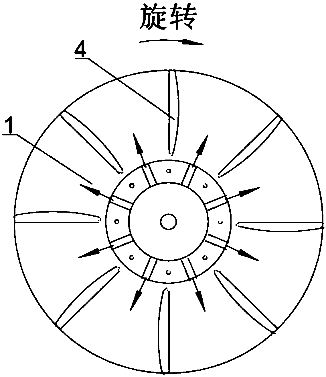
[0018] It includes a circular cover plate, the upper part of the circular cover plate is provided with an upper blade and an upper air dispersing device, the lower part of the circular cover plate is provided with a lower blade and a lower air dispersing device, and the middle of the circular cover plate An inner air passage hole is provided, and the inner passage of the lower air dispersion device communicates with the inner passage of the upper air dispersion device through the inner air passage hole.

[0019] The inner side of the lower blade is straight, the outer edge is double hypotenuse, the bottom is narrow and the...


PUM


Abstract

The invention discloses a flotation machine impeller for increasing the width of a conveying area. The flotation machine impeller comprises a circular cover plate. The upper portion of the circular cover plate is provided with an upper blade and an upper air dispersing device. The lower portion of the circular cover plate is provided with a lower blade and a lower air dispersing device. An inner air channel hole is formed in the middle of the circular cover plate. An inner channel of the lower air dispersing device is communicated with an inner channel of the upper air dispersing device through the inner air channel hole. By means of the upper blade, ore pulp above the impeller is stirred and guided air is dispersed with force, and therefore the circulation of the ore pulp at the bottom ofa flotation machine and the dispersion of the guided air are fused by means of the upper blade and the lower blade, the upper limit width of the conveying area of the flotation machine is increased,the requirements for powerfully stirring the ore pulp and dispersing the air in a stirring and mixing area of the flotation machine are met, and the requirements for effective air dispersion and ore pulp circulation of the operation central area of the conveying area are met.

Description

technical field [0001] The invention relates to a flotation machine impeller, in particular to a flotation machine impeller with widened transport area. Background technique [0002] The flotation machine is a kind of equipment used for mineral separation under the condition of gas-liquid-solid three-phase. It is mainly composed of a driving device, a stirring shaft, an impeller, a stator and a tank. The flotation machine mainly realizes the suspension of the pulp in the flotation tank and the mineralization of the collision of useful minerals and air bubbles through impeller agitation. The impeller of the flotation machine is responsible for the functions of energy input, bubble generation and dispersion, and slurry suspension, and is the most critical component of the flotation machine. With the continuous development of large-scale flotation equipment, the impeller needs to carry greater torque, and its structural design and performance design should have the characteris...

Claims


Application Information

Patent Timeline
Patent Type & Authority Applications(China)
IPC IPC(8): B03D1/16
CPCB03D1/1493B03D1/16
Inventor 史帅星沈政昌张跃军樊学赛陈东卢世杰
Owner BGRIMM MACHINERY & AUTOMATION TECH CO LTD
Why Eureka
Try Eureka