Paper tube cutting device

A cutting device and paper tube technology, which is applied in the field of paper tube manufacturing, can solve the problems of irregular cutting edge, non-adjustable, and non-adaptive adjustment of the width of the paper tube, and achieve the effect of ensuring the cutting effect

Inactive Publication Date: 2019-01-18
湖北恒鑫纸制品股份有限公司
View PDF0 Cites 2 Cited by
  • Summary
  • Abstract
  • Description
  • Claims
  • Application Information

AI Technical Summary

Problems solved by technology

The width of the clearance space along the axial direction of the rotating roller can affect the cutting effect, however, the width of the clearance space along the axial direction of the rotating roller is usually not adjustable, resulting in too large or too small

Method used


Image

  • Paper tube cutting device
  • Paper tube cutting device
  • Paper tube cutting device

Examples


Example Embodiment

[0032] The technical solutions in the embodiments of the present invention will be clearly and completely described below in conjunction with the accompanying drawings in the embodiments of the present invention. Obviously, the described embodiments are only a part of the embodiments of the present invention, rather than all the embodiments. Based on the embodiments of the present invention, all other embodiments obtained by those of ordinary skill in the art without creative work shall fall within the protection scope of the present invention.

[0033] It should be noted that if there is a directional indication (such as up, down, left, right, front, back...) in the embodiment of the present invention, the directional indication is only used to explain that it is in a specific posture (as shown in the drawings). If the specific posture changes, the relative positional relationship, movement, etc. of the components below will also change the directional indication accordingly.

[0...


PUM


Abstract

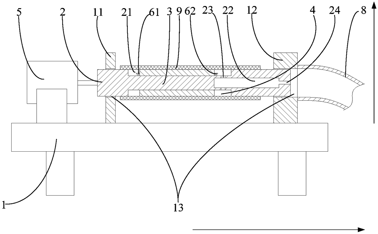
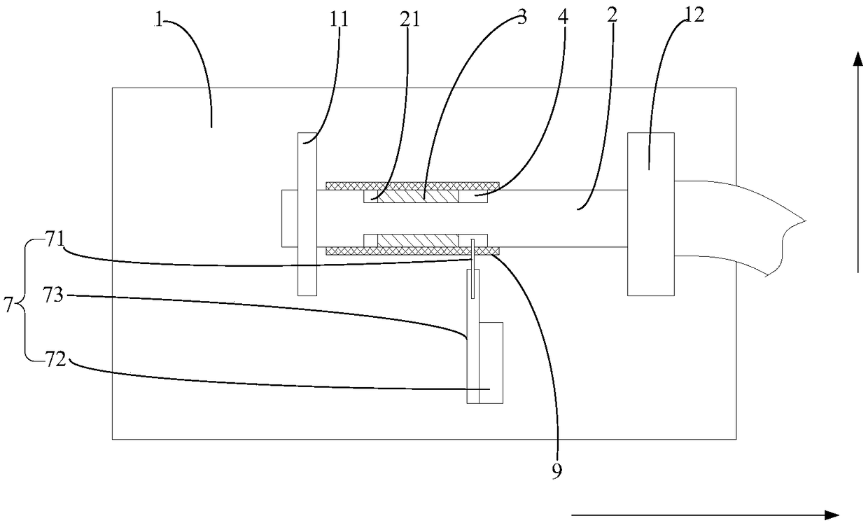
The invention provides a paper tube cutting device. The paper tube cutting device comprises a base, a rotating roller, a movable sleeve and a first driving piece. A front supporting piece and a back supporting piece are arranged on the upper side face of the base through protruding, and are each provided with an installing hole. The rotating roller is located between the front supporting piece andthe back supporting piece, and an installing groove is formed in the outer side face of the middle of the rolling roller in a concave manner, and is annularly formed in the circumferential directionof the rotating roller. The movable sleeve extends in the front and back direction, is located in the installing groove, and can slidingly sleeve the rotating roller in the front and back direction, and the end face of the back end of the movable sleeve and the inner side face, facing the front end, of the installing groove are arranged at intervals to form an abdicating space for feeding a cutting knife to extend. The first driving piece is in driving connection to the front end of the rotating roller. According to the paper tube cutting device, the abdicating space on the rolling roller is adjustable to guarantee the cutting effect on a paper tube.

Description

Technical field [0001] The invention relates to the technical field of paper tube manufacturing, in particular to a device for facilitating the cutting of paper tubes. Background technique [0002] Films, cables, toilet paper, etc. usually need to be wound on a paper tube to facilitate transportation and sale, and the paper tube is usually formed by multiple layers of recycled paper wound on a rotating roller and bonded. The formed paper tube needs to be cut into multiple sections according to the required length to facilitate the transportation and use of the paper tube. The cutting can be performed directly on the rotating roller around the paper tube, specifically, the paper tube on the rotating roller can be cut by a rotating cutting knife. In order to prevent the cutting knife from directly contacting the rotating roller during the cutting process, an annular groove can be recessed along the circumference of the rotating roller to form a space for the cutting knife to exten...

Claims


Application Information

Patent Timeline
IPC IPC(8): B26D7/01
CPCB26D7/01B26D2007/013
Inventor 赵尚策
Owner 湖北恒鑫纸制品股份有限公司
Why Eureka
Try Eureka