
Focusing device and focusing method of laser cutting machine

A laser cutting machine, focusing mirror technology, applied in laser welding equipment, welding equipment, metal processing equipment and other directions, can solve the problems of error, affecting cutting effect, cutting surface traces, etc. Effect of high gas jet velocity

Active Publication Date: 2020-05-19
JINAN BODOR LASER CO LTD
View PDF8 Cites 7 Cited by
  • Summary
  • Abstract
  • Description
  • Claims
  • Application Information

AI Technical Summary

Problems solved by technology

[0004] Ideally, the relationship between the position of the focusing mirror and the focus position is determined, and the distance between the laser and the workpiece surface is calculated according to the position of the focusing mirror, and the distance control is realized through the distance measuring mechanism. The position of the focusing lens to determine the focus position is likely to cause a large error, which will cause problems when approaching the focus, resulting in obvious marks on the cutting surface and affecting the cutting effect

Method used


Image

  • Focusing device and focusing method of laser cutting machine
  • Focusing device and focusing method of laser cutting machine
  • Focusing device and focusing method of laser cutting machine

Examples


Embodiment Construction

[0033] The present invention will be further described below in conjunction with the accompanying drawings and embodiments.

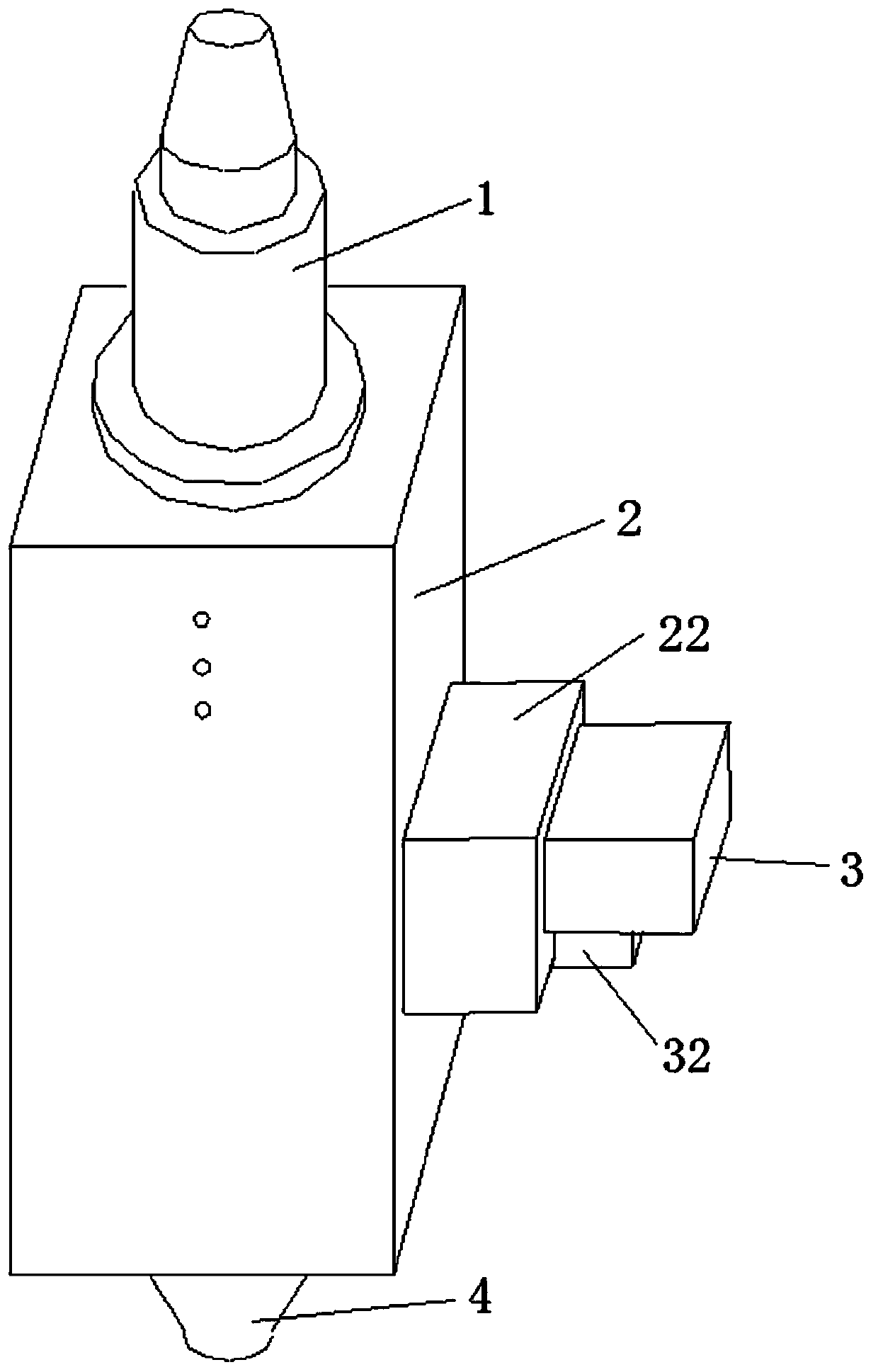
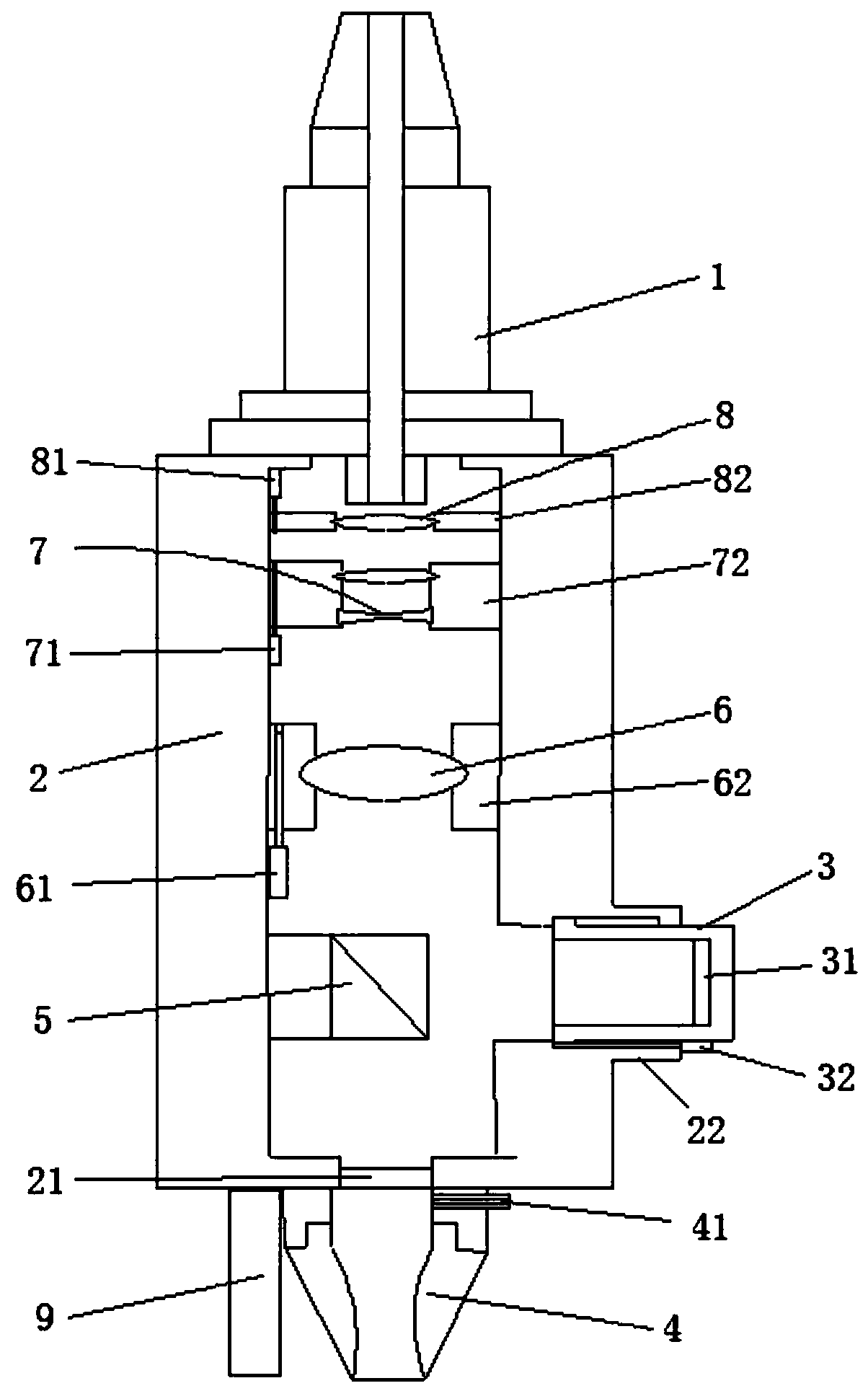
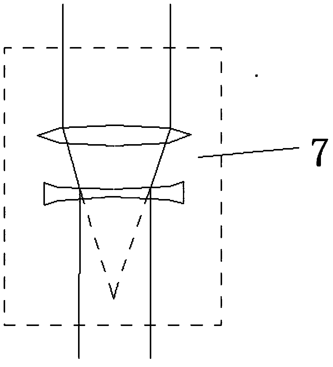
[0034] Please refer to figure 1 , figure 2 , image 3 as well as Figure 4 ,in figure 1 A structural schematic diagram of a preferred embodiment of the laser cutting machine focusing device provided by the present invention; figure 2 for figure 1 The schematic diagram of the internal structure of the focusing device of the laser cutting machine shown; image 3 for figure 2 The schematic diagram of the converging lens group and its optical path shown; Figure 4 for figure 2 Schematic diagram of the optical path of the focusing mirror, beam splitting lens and photosensitive mechanism shown.

[0035] combined reference figure 1 and figure 2 As shown, a laser cutting machine focusing device includes a housing 2, the housing 2 is a cuboid structure, the housing 2 is provided with a chamber along the length direction, the chamber is cuboid, an...


PUM


Abstract

The invention provides a focusing device of a laser cutting machine. The focusing device comprises an optical fiber joint, a shell, a sleeve, a sliding barrel, a light sensing mechanism, a linear motor, a protective mirror, a nozzle, a distance measuring mechanism, a beam splitter prism and a lens set. The optical fiber joint is arranged at one end of the shell. The sleeve is arranged on the sidewall of the shell and is provided with the sliding barrel in a sliding manner. The linear motor drives the sliding barrel to move. The light sensing mechanism is arranged in the sliding barrel. The beam splitter prism and the lens set are arranged in the shell. The protective mirror and the nozzle are arranged at the other end of the shell. According to the focusing device of the laser cutting machine, through multiple times of quantitative moving of the sliding barrel, the focal position is measured precisely, the focal position and the preset focal position are compared to form feedback, andtherefore focusing is achieved more precisely; and after precise focusing, the distance measuring mechanism is used for cooperating with a controller to adjust the laser cutting machine, it is guaranteed that the focal point is located on the surface of a workpiece, and the workpiece cutting effect is guaranteed.

Description

technical field [0001] The invention relates to the field of laser cutting equipment, in particular to a laser cutting machine focusing device and a focusing method thereof. Background technique [0002] Laser cutting is to scan the surface of the material with a focused laser beam of high power density, heat the material to thousands or even tens of thousands of degrees Celsius in a very short time, so that the material is instantly melted or vaporized, and then the molten or vaporized material is removed from the cutting process by high-pressure gas. Blow away in the seam, so as to achieve the purpose of cutting the material. [0003] At present, the laser is often equipped with a focusing device, and the laser passes through the focusing lens in the focusing device again to reach the cutting surface; in order to obtain the best cutting effect, the focusing knob on the focusing device can be rotated to adjust the focusing mirror to change the laser beam. The optical path ...

Claims


Application Information

Patent Timeline
Patent Type & Authority Applications(China)
IPC IPC(8): B23K26/046B23K26/38
CPCB23K26/046B23K26/38
Inventor 杨绪广于飞路世强韩小鹏
Owner JINAN BODOR LASER CO LTD
Learn More