Incoming fabric beating de-dusting device of circular screen printer

A technology of dust removal device and rotary screen printing, applied in screen printing machine, printing machine, rotary printing machine, etc. Facial dust removal effect, improved bristle effect, improved flapping effect

Active Publication Date: 2019-01-18
ZHEJIANG MIZUDA TEXTILE PRINTING & DYEING TECH CO LTD
View PDF7 Cites 7 Cited by
  • Summary
  • Abstract
  • Description
  • Claims
  • Application Information

AI Technical Summary

Problems solved by technology

[0002] During the printing process of the rotary screen printing machine, the cleanliness of the supplied semi-bleached fabric is very high. However, the printed semi-bleached blank provided by the pre-treatment is more or less full of floating dust such as grains and hair ash. During the printing process, impurities on the cloth surface are easily reversed to the screen cylinder, resulting in network blockage, and some impurities that have not been reversed to the network will fall off during the subsequent washing process, resulting in exposed fabric defects, which will seriously affect The quality of printed products
Existing rotary screen printing machines are generally equipped with a dust suction device in front of the cloth feeding end to carry out simple suction and dust suction for impurities. Some floating dust is adhered to the cloth surface, so simple suction and dust suction will not be effective in actual production. It is not easy to be sucked away, making the dust removal effect unsatisfactory
Therefore, the prior art has the problem of unsatisfactory dedusting effect

Method used


Image

  • Incoming fabric beating de-dusting device of circular screen printer
  • Incoming fabric beating de-dusting device of circular screen printer
  • Incoming fabric beating de-dusting device of circular screen printer

Examples


Embodiment Construction

[0022] The present invention will be further described below in conjunction with the accompanying drawings and embodiments, but not as a basis for limiting the present invention.

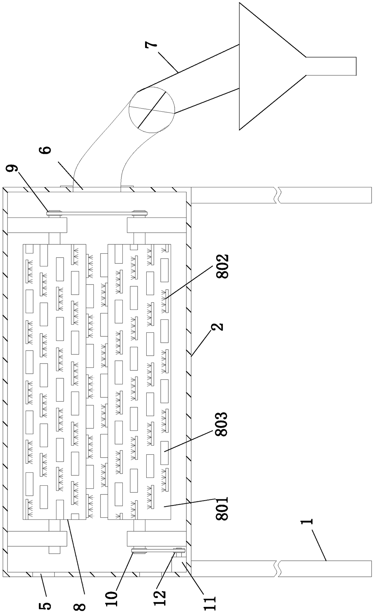
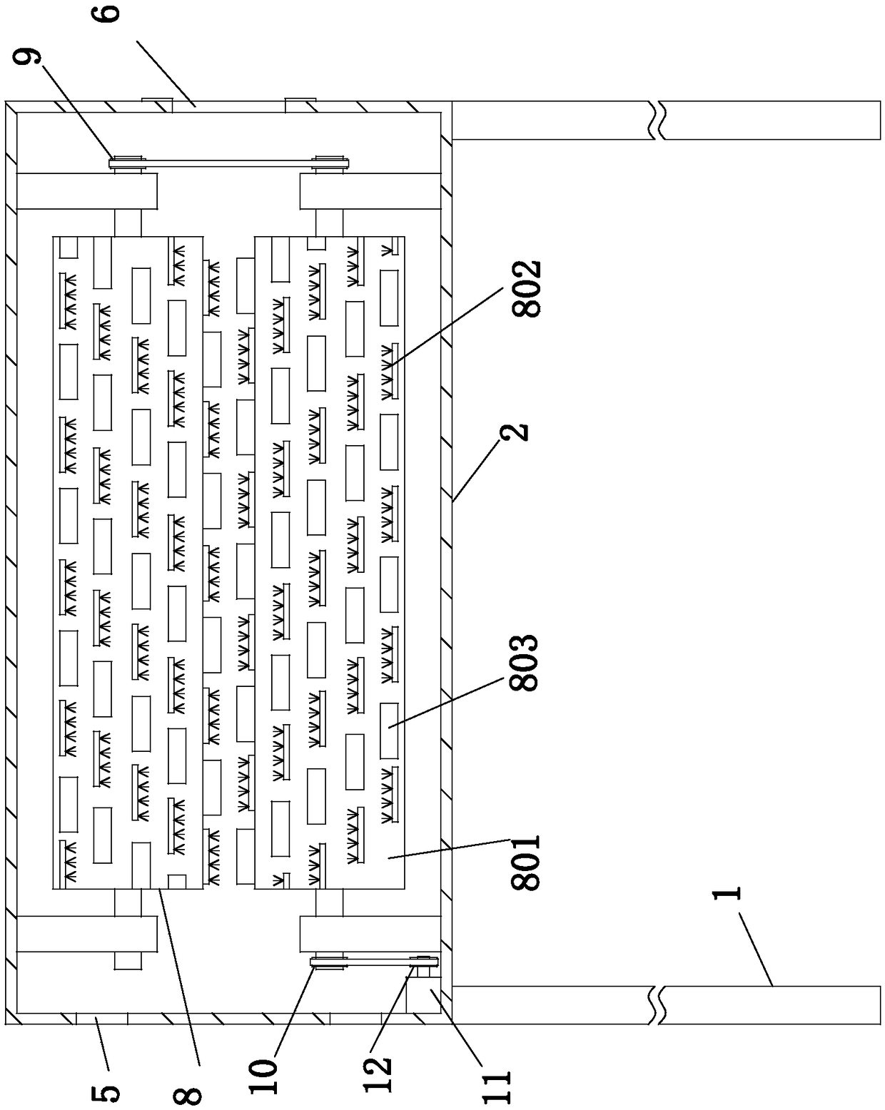
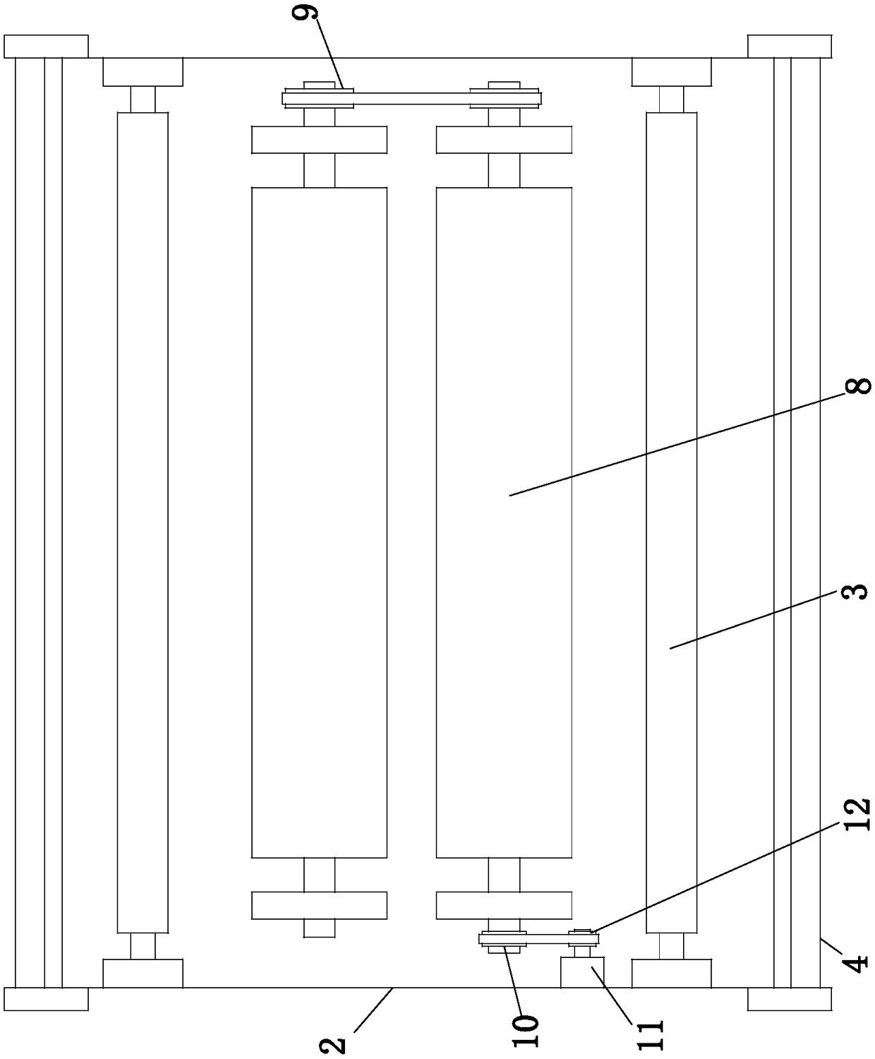
[0023] Example. A rotary screen printing machine feeds the cloth and pats the dust removal device, which is composed of Figure 1 to Figure 5 As shown, it includes a support frame 1, a dust removal box 2 is arranged on the support frame 1, a beating dust removal mechanism is arranged in the dust removal box 2, cloth pressing rollers 3 are respectively arranged on the front and rear sides of the beating dust removal mechanism, and the front and rear sides of the dust removal box 2 Cloth inlets and outlets are respectively provided, and cloth guide rollers 4 are provided on the cloth inlets and outlets, and the two ends of the dust removal box 2 are respectively provided with air inlets 5 and suction outlets 6, and the suction outlets 6 are connected with dust collectors. Mechanism 7; the beating and...


PUM


Abstract

The invention discloses an incoming fabric beating de-dusting device of a circular screen printer. The incoming fabric beating de-dusting device comprises a supporting frame, a de-dusting box is arranged on the supporting frame, a beating de-dusting mechanism is arranged in the de-dusting box, the front side and the rear side of the beating de-dusting mechanism are provided with fabric compressionrollers respectively, and a fabric inlet and a fabric outlet are formed in the front side and the rear side of the de-dusting box. Fabric guide rollers are arranged at the fabric inlet and the fabricoutlet respectively, an air inlet and an exhaust inlet are formed in the two ends of the de-dusting box respectively, and the exhaust inlet is connected with a dust collection mechanism. The beatingde-dusting mechanism comprises two beating de-dusting rollers which are arranged up and down, the beating de-dusting rollers comprise roller bodies, and the surfaces of the roller bodies are providedwith two brush assemblies and two beating assemblies, wherein the brush assemblies and the beating assemblies are helically distributed. The incoming fabric beating de-dusting device has the advantages of being capable of effectively improving the de-dusting effect.

Description

technical field [0001] The invention relates to a cloth feeding and dedusting device for a rotary screen printing machine, in particular to a cloth feeding and beating dedusting device for a rotary screen printing machine. Background technique [0002] During the printing process of the rotary screen printing machine, the cleanliness of the supplied semi-bleached fabric is very high. However, the printed semi-bleached blank provided by the pre-treatment is more or less full of floating dust such as grains and hair ash. During the printing process, impurities on the cloth surface are easily reversed to the screen cylinder, resulting in network blockage, and some impurities that have not been reversed to the network will fall off during the subsequent washing process, resulting in exposed fabric defects, which will seriously affect The quality of printed products. Existing rotary screen printing machines are generally equipped with a dust suction device in front of the cloth ...

Claims


Application Information

Patent Timeline
Patent Type & Authority Applications(China)
IPC IPC(8): B41F15/12B41F23/00D06G1/00
CPCB41F15/12B41F23/002D06G1/00
Inventor 李祥波
Owner ZHEJIANG MIZUDA TEXTILE PRINTING & DYEING TECH CO LTD
Why Eureka
Try Eureka