Burner installation for increased safety

A burner and safety technology, applied in the field of burner devices to improve safety, can solve the problems of dangerous flashing, prolonging burning time, maintaining fuel temperature, etc.

Active Publication Date: 2020-01-10
PRO IRODA INDS
View PDF6 Cites 0 Cited by
  • Summary
  • Abstract
  • Description
  • Claims
  • Application Information

AI Technical Summary

Problems solved by technology

With the combustion device with the above structure, when the flame scale is too large or the enlarged fuel tank is used for a long time, when the heat accumulated to the fuel tank on both sides of the flame and the device below it through conduction and radiation is too much, it may cause the fuel tank on the ground The temperature in the tank is too high, when the temperature of the fuel in the tank is higher than the flash point, it will cause a dangerous flash fire
Because the above-mentioned design still has insufficient insulation effect on radiation and conduction heat, if the scale of the flame is increased or the burning time is to be prolonged, the design of the combustion device with the above-mentioned structure is still used, and the fuel tank cannot be extended only by enlarging the fuel tank. time to keep the fuel temperature at a relatively safe low temperature

Method used


Image

  • Burner installation for increased safety
  • Burner installation for increased safety
  • Burner installation for increased safety

Examples


Embodiment Construction

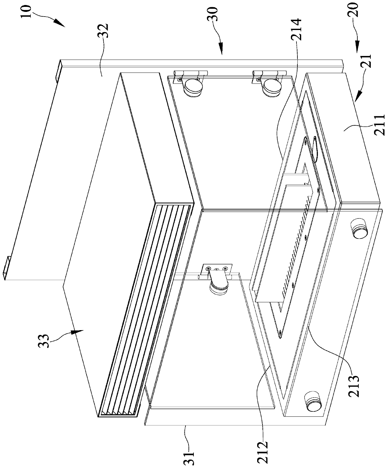
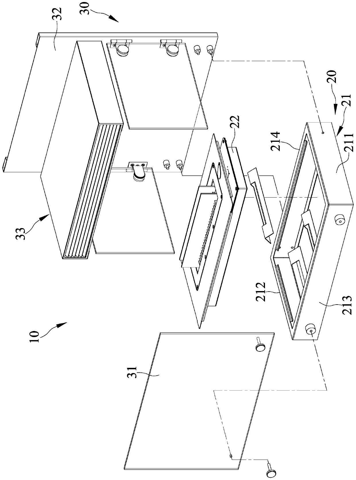
[0020] Please refer to Figure 1 to Figure 5 Shown is the three-dimensional appearance view, three-dimensional exploded view and cross-sectional structure view of the safety-improving burner device of the present invention. The burner device 10 of the present invention includes a furnace body 20 and a diversion module 30; wherein:

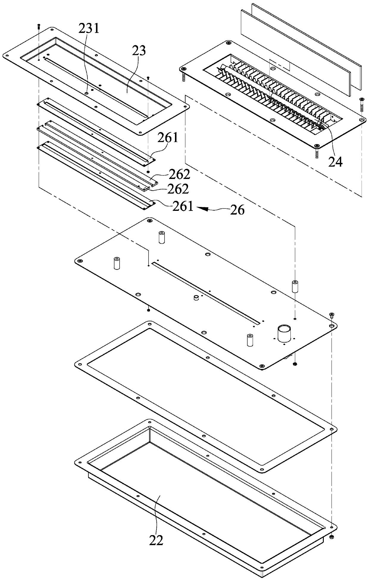
[0021] The furnace body 20 includes a shell 21, a fuel tank 22, a fuel tray 23 and a candle wick 24. The shell 21 includes a first end 211 and a second end 212. The first end 211 of the shell 21 The second end 212 is the two different ends of the housing 21 along the horizontal direction, the housing 21 includes a first side 213 and a second side 214, the first side 213 and the second side 214 are the housing 21 on different sides along the other horizontal direction. The fuel tank 22 is disposed in the casing 21, the fuel tray 23 is connected to the top side of the casing 21, the fuel tray 23 is located above the fuel tank 22 along the vertical ...


PUM


Abstract

The safety-improving burner device of the present invention includes a furnace body, the furnace body includes a fuel tank, a fuel pan and a candle wick, the fuel pan is located above the fuel tank along the vertical direction, and the fuel pan The tank body that is not directly connected to the fuel tank, the ignition and burning end of the candle wick is set in the fuel tray, and the lower end of the candle wick along the vertical direction is set in the fuel tank, because the fuel will generate high temperature when burning, for To avoid direct transmission of the high temperature of the fuel to the fuel tank, the burner device adopts the design that the fuel plate is not directly connected to the fuel tank to effectively isolate the transfer of heat energy and ensure that the fuel in the fuel tank can be kept at a safe low temperature. state, thereby improving the safety of the burner device.

Description

technical field [0001] The invention mainly discloses a burner device, especially a burner device with improved safety. Background technique [0002] Please refer to the "Safe combustion device" patent case of US Patent No. US 9651246, which discloses a safe combustion device, which includes a body and a flow guide module, the body is provided with an accommodating space and a set of candles The wick, the wick is arranged in the semi-open space formed by the top diversion module, the body has a bottom surface, the candle wick includes a top, the top of the candle wick has a first distance from the bottom surface, the diversion module is connected to the body, the diversion module Including a first shielding member, the first shielding member includes a bottom side and a top side, the bottom side and the bottom surface have a second distance not greater than the first distance, and the top side and the bottom surface have a distance greater than the first distance The third ...

Claims


Application Information

Patent Timeline
Patent Type & Authority Patents(China)
IPC IPC(8): F23D3/02F23D3/18F24C5/04F24D15/02
CPCF23D3/02F23D3/18F24C5/04F24D15/02F23D2900/31005
Inventor 陈维隆
Owner PRO IRODA INDS
Why Eureka
Try Eureka