Eureka AIR delivers breakthrough ideas for toughest innovation challenges, trusted by R&D personnel around the world.

Impact strength testing machine for axillary crutch

An impact strength and testing machine technology, applied in the direction of strength characteristics, measuring devices, instruments, etc., can solve the problems of complex impact methods, affecting the accuracy of impact performance testing of axillary crutches, and safety threats to test personnel, and achieve the effect of ensuring safety.

Active Publication Date: 2019-01-18
SHANGHAI UNIV
View PDF8 Cites 1 Cited by
  • Summary
  • Abstract
  • Description
  • Claims
  • Application Information

AI Technical Summary

Problems solved by technology

This method can effectively use the heavy hammer to impact the armpit handle for strength testing, but the impact method is complicated, the test and debugging are inconvenient, and the stability of the expansion and contraction of the cylinder cannot be controlled.
In addition, most of the current impact testing machines cannot flexibly adjust the posture of the axil crutches, and most of them adjust the axil crutches as a whole in the front and rear directions.
In addition, the bare metal form poses a potential threat to the safety of experimenters
These three points greatly affect the accuracy of the impact performance test of the axillary crutches

Method used


Image

  • Impact strength testing machine for axillary crutch
  • Impact strength testing machine for axillary crutch
  • Impact strength testing machine for axillary crutch

Examples


Embodiment Construction

[0017] Preferred examples of the present invention are described as follows in conjunction with accompanying drawings:

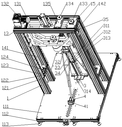
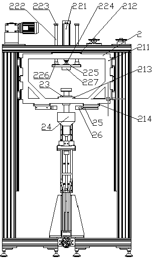
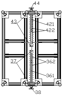
[0018] Such as Figure 1 to Figure 3 As shown, a crutch impact strength testing machine includes a support 1, a frame mechanism for moving up and down 2, an armrest posture adjustment mechanism 3, a foot posture adjustment mechanism 4, a protective net and a control box; it is characterized in that: the upper and lower The left and right sides of the mobile frame 2 are fixedly connected with the T nuts connected to the two lead screws 141 and 142 between the bracket 1, the motor 131 is connected to the reducer 132, the extension shaft of the reducer 132 is connected to the active lead screw 141 through a coupling, and the drive The rod 141 drives the driven screw 142 to rotate synchronously through the transmission of the sprockets 133 and 134, thereby driving the up and down movement of the frame 2 including the weight 24 to move up and down, and the postur...


PUM


Abstract

The invention provides an impact strength testing machine for an axillary crutch. The impact strength testing machine comprises a bracket, an upper and lower moving frame mechanism, an armpit supportposition and posture adjusting mechanism, a supporting leg position and posture adjusting mechanism, a protective net and a control box. The left side and the right side of the upper and lower movingframe are fixedly connected with T-shaped nuts which are connected with two leadscrews between the bracket. A motor is connected with a speed reducer. An extension shaft of the speed reducer is connected with a driving leadscrew through a coupler. The driving leadscrew drives a driven leadscrew to rotate synchronously through a chain wheel transmission so as to drive the upper and lower moving frame and a heavy hammer to move up and down. The position and posture of the axillary crutch is adjusted through the armpit support position and posture adjusting mechanism and the supporting leg position and posture adjusting mechanism. The control box is fixedly connected to a vertical profile on the right side of the bracket. The protective net is mounted on the periphery of the testing machine.A touch screen is connected onto the protective net. A first hand wheel is rotated to achieve height adjustment of the armpit support; a second hand wheel is rotated to achieve front and back adjustment of the armpit support; and a third hand wheel is rotated to achieve front and back adjustment of the supporting legs whose height is fixed. According to the impact strength testing machine for theaxillary crutch, electromagnet is adopted for carrying out power-on lifting and power-off releasing of the heavy hammer to realize the drop weight impact test.

Description

technical field [0001] The invention relates to an impact strength testing device, in particular to an impact strength testing machine of an armpit crutch, which belongs to the field of impact performance testing of an armpit crutch. Background technique [0002] With the increasing aging of the social population, the use of rehabilitation aids in people with disabilities has become increasingly widespread, and axillary crutches have become one of the most commonly used rehabilitation aids. Due to the dysfunction of the user's own body, the quality of the crutches is directly related to the safety of the users, so it is necessary to test the impact performance of the crutches. At present, in China, mechanical clamps are often used to lift and release heavy hammers to impact the handle of axillary crutches. The posture of the axillary crutches is fixed, and the impact part of the test equipment uses two cylinders. Cylinder 1 telescopically pushes the manipulator to move up a...

Claims


Application Information

Patent Timeline
Patent Type & Authority Applications(China)
IPC IPC(8): G01N3/303
CPCG01N3/303
Inventor 王志明崔利贞蔡正龙庞长富叶王伟
Owner SHANGHAI UNIV
Why Eureka
Eureka Blog
Learn More