Transmission line, and scattering parameter testing system and method

A scattering parameter test and transmission line technology, applied in the direction of measuring electricity, measuring devices, measuring electrical variables, etc., can solve the problems of low production efficiency, inconsistency, and difficulty in adapting to industrial production needs, so as to achieve convenient operation and improve production Effects of efficiency and stable electrical performance

Active Publication Date: 2019-01-18
SOUTH CHINA UNIV OF TECH +1
View PDF8 Cites 10 Cited by
  • Summary
  • Abstract
  • Description
  • Claims
  • Application Information

AI Technical Summary

Problems solved by technology

[0003] However, the "de-embedding" testing technology commonly used in the above-mentioned prior art cannot be applied in occasions where the scattering parameters of the first module under test cannot be measured, for example, when the first module under test is a surface-mounted filter, the second The second module under test is an antenna unit. When the two are soldered on the same PCB, on the one hand, the filter cannot be disassembled and tested separately to obtain its scattering parameters; Test to obtain the scattering parameters. Since different products do not have ideal consistency, the scattering parameters measured with filters with similar functions cannot be equivalent to the scattering parameters of the filters that have been welded on the antenna unit; Although the method of testing the device separately and then assembling it into the antenna unit can accurately obtain the scattering parameters of the second module under test, it will lead to extremely low production efficiency in actual production, and it is difficult to meet the needs of industrial production

Method used


Image

  • Transmission line, and scattering parameter testing system and method
  • Transmission line, and scattering parameter testing system and method
  • Transmission line, and scattering parameter testing system and method

Examples


Embodiment Construction

[0038] In order to further illustrate the technical means adopted by the present invention and the achieved effects, the technical solutions of the present invention will be clearly and completely described below in conjunction with the accompanying drawings and preferred embodiments.

[0039] It should be noted that when an element is referred to as being "fixed" or "disposed on" another element, it can be directly on the other element or there may be intervening elements at the same time. When an element is referred to as being "connected" to another element, it can also be directly connected to the other element or intervening elements may also be present.

[0040] In the description of the present invention, it should be understood that the terms "first" and "second" are used for description purposes only, and cannot be interpreted as indicating or implying relative importance or implicitly indicating the quantity of indicated technical features. Thus, a feature defined as...


PUM


Abstract

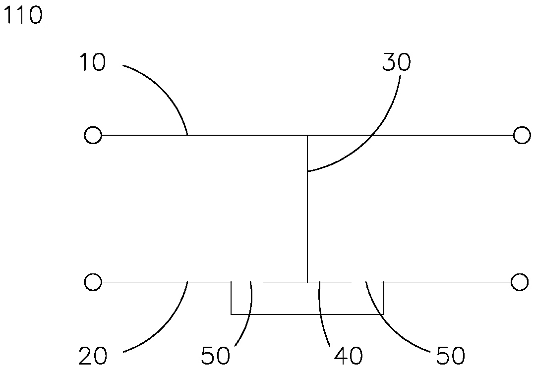
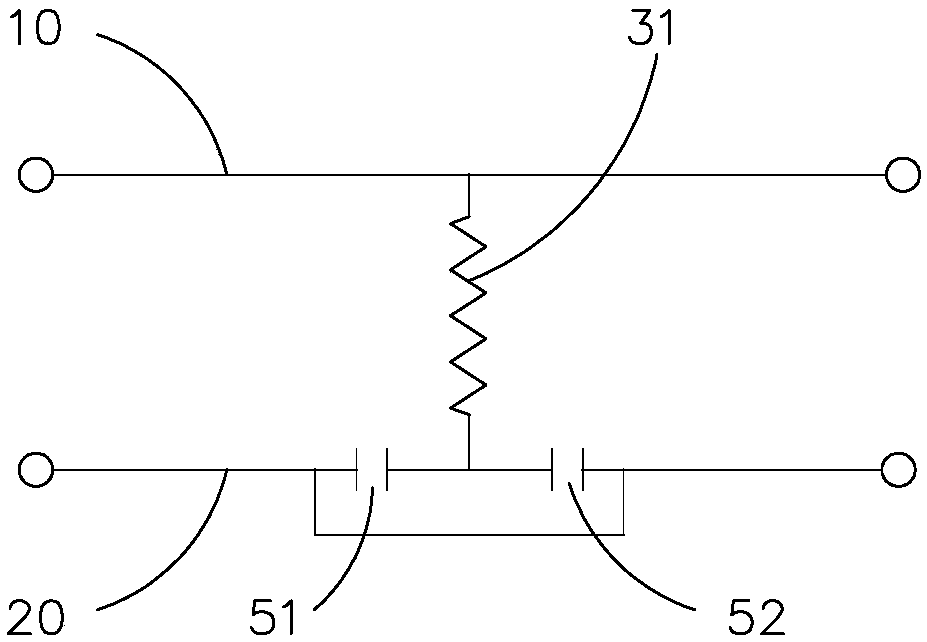
The invention relates to a transmission line, and a scattering parameter testing system and method. The transmission line comprises a first conducting line and a second conducting line which are usedfor transmitting radio frequency signals; a connecting line is arranged between the first conducting line and the second conducting line; the connecting line includes a first connecting line and a second connecting line; the first connecting line has a first end and a second end; the first connecting line is connected with the first conducting line through the first end, and the first connecting line is connected with the second connecting line through the second end; and the second connecting line is a coupling line in coupling connection with the second conducting line. The stability and theconsistency are relatively high, and an individual test can be performed to obtain scattering parameters. The coupling line of the transmission line can be externally connected with a calibration part, and the scattering parameters used for calculating a required test result can be obtained by changing electrical parameters of the calibration part, so that a "de-embedding" test is achieved; and afirst tested module with the relatively poor consistency does not need to be measured, so that the test process is simple and convenient, and the error is small.

Description

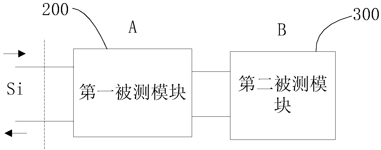
technical field [0001] The invention relates to the technical field of radio frequency testing, in particular to a transmission line, a scattering parameter testing system and a method using the transmission line. Background technique [0002] In RF testing, scattering parameter measurements are often required. Scattering parameters (scattering parameters) are also called S parameters. In the existing scattering parameter test, the "de-embedding" test technique is often used, please refer to figure 1 As shown, when the first module under test 200 is also included between the second module under test 300 and the vector network analyzer (the main test instrument used to measure scattering parameters, not shown), the vector network analyzer starts from the first module under test The port reflection coefficient S measured by the measuring module 200 0 In fact, it is the result of cascading the scattering parameter B of the second module under test 300 and the scattering para...

Claims


Application Information

Patent Timeline
Patent Type & Authority Applications(China)
IPC IPC(8): G01R31/00
CPCG01R31/00
Inventor 赖展军李明超冯穗力
Owner SOUTH CHINA UNIV OF TECH
Why Eureka
Try Eureka