Connector welding test device

A test device and connector technology, applied in the field of testing, can solve problems such as time-consuming, poor welding, occupation of manpower and material resources, etc., and achieve the effect of saving maintenance costs, improving work efficiency, and reducing the time spent on measurement

Inactive Publication Date: 2019-01-18
HONG FU JIN PRECISION IND WUHAN CO LTD +1
View PDF0 Cites 0 Cited by
  • Summary
  • Abstract
  • Description
  • Claims
  • Application Information

AI Technical Summary

Problems solved by technology

[0002] The main circuit board of existing electronic equipment generally has one or more connectors soldered, such as USB type connectors, video/audio interface connectors, etc. These connectors include multiple pins, and poor soldering may occur
When a connector communicati

Method used


Image

  • Connector welding test device
  • Connector welding test device
  • Connector welding test device

Examples


Example Embodiment

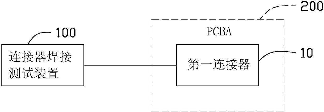
[0019] See Figure 1-3 An embodiment of the present invention provides a connector welding test device 100. The connector welding test device 100 can test the first connector 10 welded on the PCBA 200, which can be a notebook computer motherboard, a server motherboard, or the like.

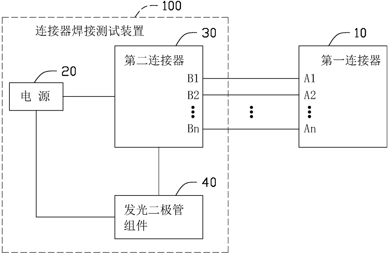
[0020] The connector welding test device 100 includes a power source 20, a second connector 30 and a light emitting diode assembly 40. The light-emitting diode assembly 40 includes a plurality of light-emitting diodes LED1-LEDm (m is an integer and m> 1). The second connector 30 is matched with the first connector 10 and can be inserted into each other. That is, the first connector 10 and the second connector 30 are preferably connectors of the same model, the first connector 10 is preferably a female connector, and the second connector 30 is preferably a male connector. The first connector 10 includes a plurality of pins A1 to An, and the second connector 30 includes a plurality of pins B1 to Bn. ...


PUM


Abstract

The invention provides a connector welding test device for testing a first connector welded on a PCBA. The connector welding test device comprises a power source, a second connector, and a plurality of light emitting diodes. The second connector is matched with the first connector, and the first connector and the second connector respectively comprise a plurality of pins. A positive electrode of the power source is electrically connected with the first pin of the second connector, and the positive electrode of each light emitting diode is electrically connected with the second pin to the Nth pin of the second connector in a one-to-one correspondence manner, and a negative electrode of each light emitting diode is electrically connected with the negative electrode of the power source. Whenthe second connector is plugged into the first connector, the welding state of each pin of the first connector and the PCBA is judged according to the light emitting state of each light emitting diode. The connector welding test device can quickly measure the welding state of the connector through the light emitting diodes, thereby effectively shortening the time taken for the measurement.

Description

technical field [0001] The invention relates to the technical field of testing, in particular to a connector welding testing device. Background technique [0002] One or more connectors, such as USB type connectors, video / audio interface connectors, etc., are generally welded on the main circuit board of existing electronic equipment. These connectors include multiple pins, and poor soldering may occur. When a connector communication failure is found during the test, the tester can only rely on the tester to measure each pin of the connector in turn through the test instrument. If the connector has many pins, it will take a lot of time to test, which takes up a lot of human and material resources. Contents of the invention [0003] In view of the above, it is necessary to provide a connector welding test device, which can effectively reduce the measurement time. [0004] One embodiment of the present invention provides a connector welding test device for testing a first ...

Claims


Application Information

Patent Timeline
IPC IPC(8): G01R31/04
CPCG01R31/66
Inventor 史建雄邹立洪张争
Owner HONG FU JIN PRECISION IND WUHAN CO LTD
Why Eureka
Try Eureka