
LED light-emitting panel and preparation method thereof, LED display screen

A technology of light-emitting panels and circuit substrates, which is applied in the direction of instruments, electrical components, and electrical solid devices, and can solve the problems of easy reflection of transparent protective layers, low air refractive index, and decreased permeability of LED displays.

Inactive Publication Date: 2019-01-18
VITROLIGHT TECH CO LTD
View PDF4 Cites 6 Cited by
  • Summary
  • Abstract
  • Description
  • Claims
  • Application Information

AI Technical Summary

Problems solved by technology

Since there is no need to use an additional packaging structure to package the LED bare chips, the transparent protective layer can be directly arranged on the side of multiple LED bare chips away from the transparent substrate, so that there is an air layer between the transparent circuit substrate and the transparent protective layer, and the air The refractive index is low, and the transparent protective layer is prone to reflect light, resulting in a decrease in the permeability of the LED display and affecting its display effect

Method used


Image

  • LED light-emitting panel and preparation method thereof, LED display screen
  • LED light-emitting panel and preparation method thereof, LED display screen
  • LED light-emitting panel and preparation method thereof, LED display screen

Examples


Embodiment Construction

[0028] The present invention will be further described in detail below in conjunction with the accompanying drawings and embodiments. It should be understood that the specific embodiments described here are only used to explain the present invention, but not to limit the present invention. In addition, it should be noted that, for the convenience of description, only parts related to the present invention are shown in the drawings but not all content. Before discussing the exemplary embodiments in more detail, it should be mentioned that some exemplary embodiments are described as processes or methods depicted as flowcharts. Although the flowcharts describe various operations (or steps) as sequential processing, many of the operations may be performed in parallel, concurrently, or simultaneously. In addition, the order of operations can be rearranged. The process may be terminated when its operations are complete, but may also have additional steps not included in the figure...


PUM


Abstract

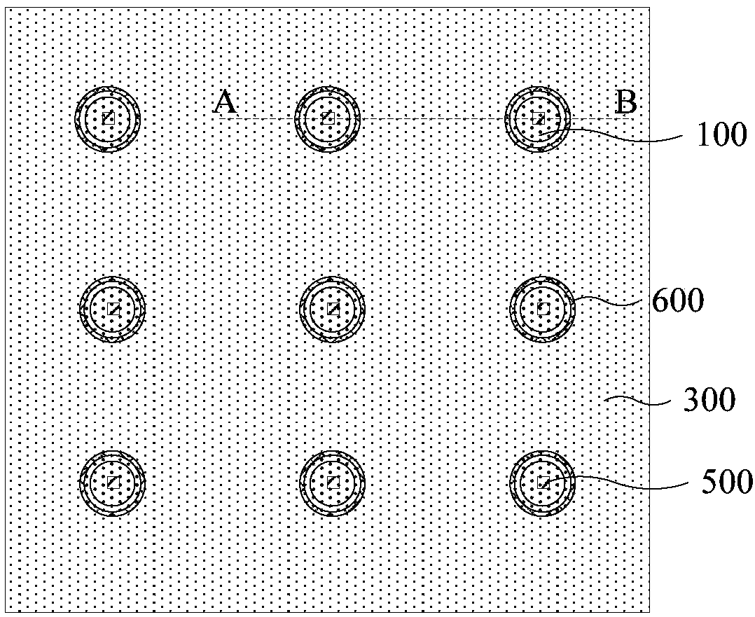
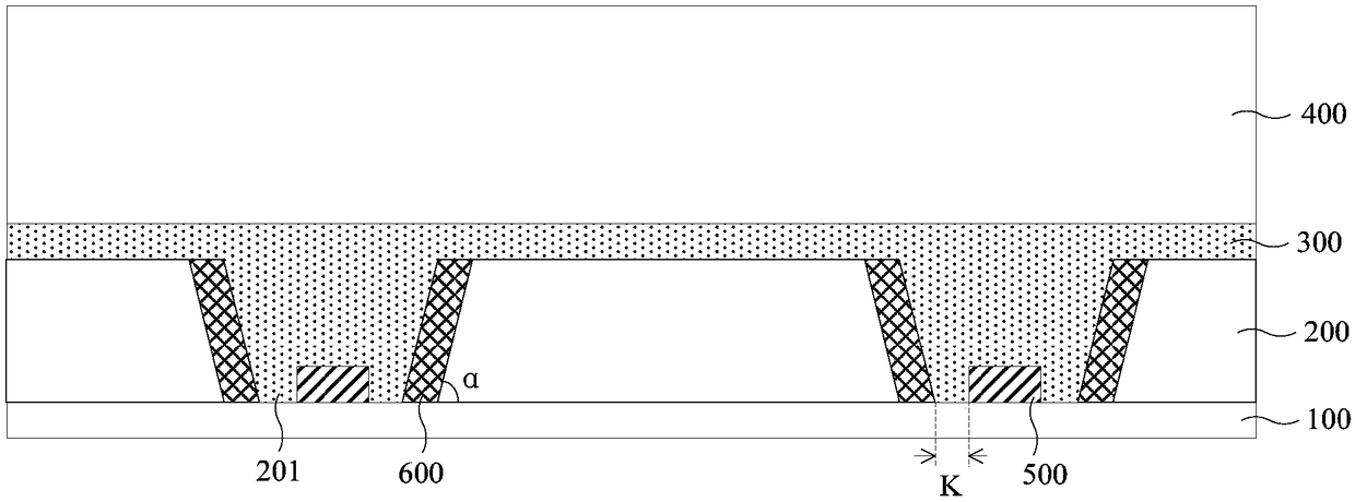
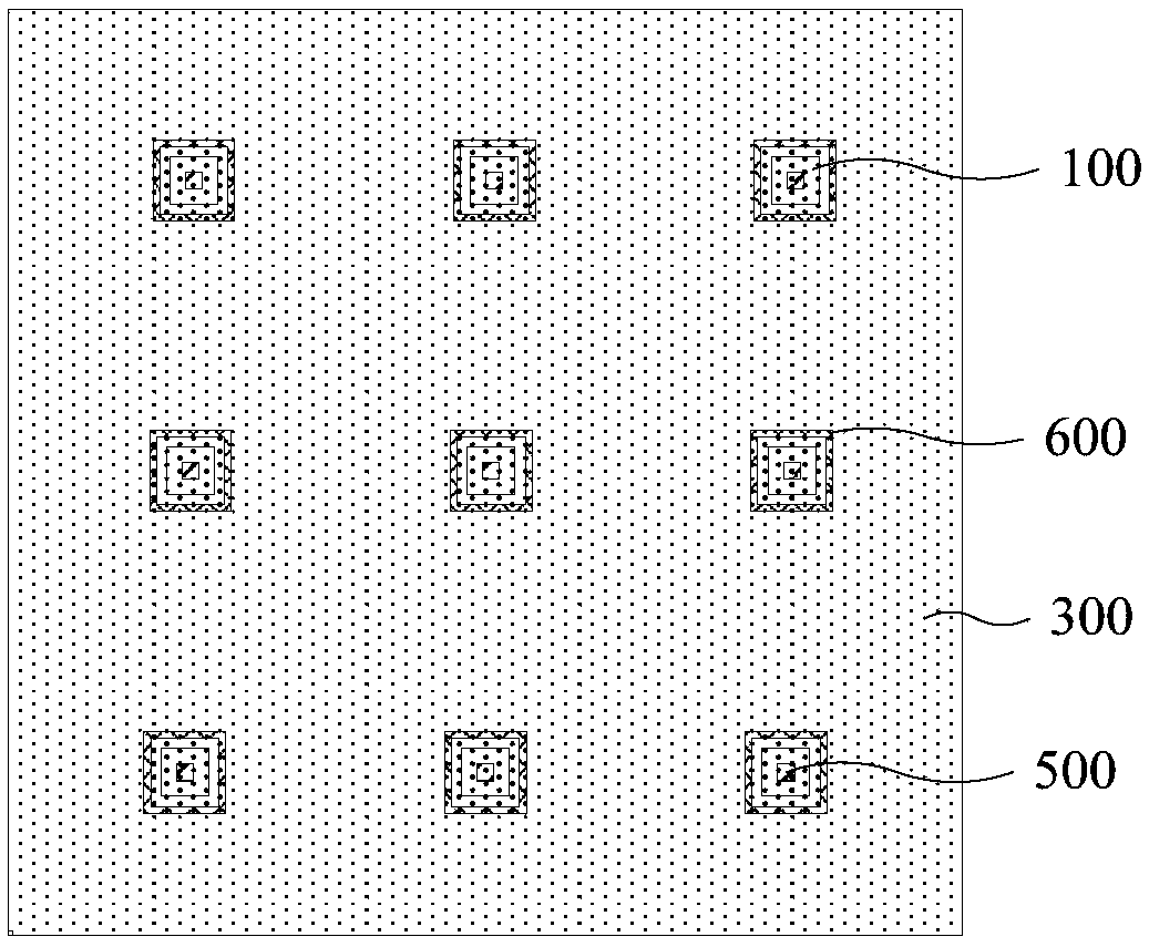
The invention discloses an LED light-emitting panel and a preparation method thereof, and an LED display screen. The LED light-emitting panel comprises a transparent circuit substrate, a plurality ofLED bare chips, a transparent isolation layer, a reflective layer, a transparent refractive adhesive layer and a transparent protective layer. The transparent isolation layer is arranged on the transparent circuit substrate, the transparent isolation layer comprises a plurality of through holes, the through holes penetrate through the transparent isolation layer to expose part of the surface of the transparent circuit substrate, and an LED bare chip is mounted on the transparent circuit substrate exposed by each through hole; The reflective layer is arranged on the side wall of the through hole; A transparent refractive adhesive layer is filled in the through hole and a side of the transparent isolation layer away from the transparent circuit substrate; The transparent protective layer islocated at a side of the transparent refractive adhesive layer away from the transparent circuit substrate; Wherein the refractive index of the transparent refractive glue layer is greater than 1.5. The technical proposal provided by the embodiment of the invention increases the permeability of the LED display screen and improves the display effect of the LED display screen.

Description

technical field [0001] Embodiments of the present invention relate to transparent LED display technology, in particular to an LED light-emitting panel, a preparation method thereof, and an LED display. Background technique [0002] The transparent LED display has good display effect and has the advantage of not blocking the line of sight. It is more and more favored by the market and widely used in shopping malls, airports, banks, luxury stores and other high-end occasions. [0003] The transparent LED display screen in the prior art includes a transparent circuit substrate, a plurality of packaged LED bare chips mounted on the transparent circuit substrate, and a transparent protective layer. Since there is no need to use an additional packaging structure to package the LED bare chips, the transparent protective layer can be directly arranged on the side of multiple LED bare chips away from the transparent substrate, so that there is an air layer between the transparent cir...

Claims


Application Information

Patent Timeline
Patent Type & Authority Applications(China)
IPC IPC(8): H01L33/54H01L33/60H01L25/13G09F9/33
CPCG09F9/33H01L25/13H01L33/54H01L33/60H01L2933/005H01L2933/0058
Inventor 张君张义荣邬剑波
Owner VITROLIGHT TECH CO LTD
Learn More