
A mechanical anti-theft lock for automobile

A mechanical anti-theft lock and automobile technology, applied in the field of automotive mechanical anti-theft locks, can solve the problems of simplification of functions, difficulty in fixing, and poor practicability, and achieve the effects of diversified functions, full use of space, and low installation difficulty

Inactive Publication Date: 2019-01-22
CHONGQING COLLEGE OF ELECTRONICS ENG
View PDF9 Cites 0 Cited by
  • Summary
  • Abstract
  • Description
  • Claims
  • Application Information

AI Technical Summary

Problems solved by technology

[0005] The above-mentioned patents are difficult to fix in the process of actual use, and the equipment needs to be additionally connected to electronic control equipment, the functions are single, and the practicability is poor, so we need to make further improvements on the existing basis

Method used


Image

  • A mechanical anti-theft lock for automobile
  • A mechanical anti-theft lock for automobile
  • A mechanical anti-theft lock for automobile

Examples


Embodiment 1

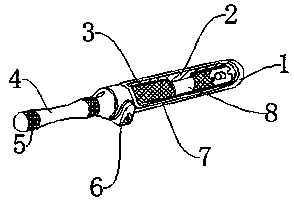
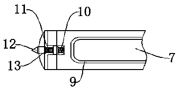
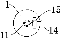
[0037] Such as Figure 1-Figure 7As shown, a kind of automobile mechanical antitheft lock of the present invention comprises antirust lock body 1, and the surface of antirust lock body 1 is provided with steering wheel placement groove 7, and the side wall of steering wheel placement groove 7 is provided with protective rubber cover 9, and antirust lock body 1. A flexible protective pad 3 is provided on the inner wall. A lock tongue 2 is provided inside the anti-rust lock body 1. A rubber-coated stopper 8 is provided on the lock tongue 2. A locking device 6 is provided at the bottom of the anti-rust lock body 1. The locking device 6. One side is provided with a metal handle 4, and the outer wall of the metal handle 4 is provided with anti-slip lines 5. The end of the anti-rust lock body 1 is provided with a safety hammer nail head 12, and a transmission rod 11 is arranged below the safety hammer nail head 12. The transmission rod 11 One side is provided with a first limiting b...

Embodiment 2

[0039] The difference between this embodiment and Embodiment 1 is:

[0040] In this embodiment, the depth range of the limiting groove 13 is not less than 5 mm, and the lock tongue 2 is provided with a through hole for fixing with the lock core 16 at a position close to the lock core 16 . This setting can improve the fixing effect of the device and increase the anti-theft capability of the device. There are two support seats 34, and the two support seats 34 are symmetrically distributed on both sides of the transmission gear 28. The anti-tilt gear 32 is fixed inside the support seat 34 by a pin, and the anti-tilt gear 32 is meshed with the rack 30, so that The setting can ensure that the rack 30 can move smoothly.

[0041] The working principle of the anti-theft lock in the present invention is: when carrying out anti-theft measures for automobiles, the operator can align the steering wheel placement groove 7 on the antirust lock body 1 with the steering wheel and embed it in...


PUM


Abstract

The invention discloses a mechanical anti-theft lock for an automobile which comprises a rust-proof lock body. A surface of that rust-proof lock body is provided with a steering wheel placing groove.A lateral wall of that steer wheel placement groove is provided with a protective rub sleeve. A flexible protective pad is arranged on the inner wall of the rust-proof lock, a locking tongue is arranged on the inner part of the rust-proof lock, a rubber-wrapped stopper is arranged on the locking tongue, a locking device is arranged on the bottom of the rust-proof lock body, a metal handle is arranged on one side of the locking device, and an anti-slip grain is arranged on the outer wall of the metal handle. The invention has the following advantages: 1, the product structure is reasonable, thespace is fully utilized, the occupying area is small, the installation difficulty is low, and the use is convenient; 2, the function are diversified, the service life is long, the failure rate is low, the function of the equipment can be used for escape in time when the automobile breaks down, and The invention has strong practicability; 3, the cylindrical design is adopted, when the malignant event occurs, the operator can use the equipment to defend himself and improve the use safety of the equipment.

Description

technical field [0001] The invention relates to the technical field of automobile anti-theft equipment, in particular to an automobile mechanical anti-theft lock. Background technique [0002] Car anti-theft locks can be basically divided into three categories according to technical principles: mechanical anti-theft locks, electronic anti-theft alarm locks, and networked anti-theft (location, tracking) systems. Car anti-theft locks include: electronic car anti-theft locks, network car anti-theft locks, oil circuit locks, clutch brake anti-theft locks, wheel anti-theft locks, gear locks, steering wheel locks, car anti-theft magnetic discs, etc. [0003] With the continuous increase of car ownership, car theft cases occur from time to time. With the continuous efforts of OEMs, the current car anti-theft measures have been perfected, but for vicious theft incidents, traditional anti-theft measures cannot satisfy The use needs at this stage require additional anti-theft equipme...

Claims


Application Information

Patent Timeline
IPC IPC(8): B60R25/022A62B3/00F41B15/00
CPCA62B3/005B60R25/022F41B15/00
Inventor 魏健东甘守武
Owner CHONGQING COLLEGE OF ELECTRONICS ENG
Learn More