Discharging mechanism

A blanking mechanism and a blanking hopper technology, applied in loading/unloading, containers, packaging, etc., can solve problems affecting material handling efficiency, jamming, etc., achieve fast and convenient dredging, and ensure normal delivery.

Pending Publication Date: 2019-01-22
广西玉柴专用汽车有限公司
View PDF0 Cites 0 Cited by
  • Summary
  • Abstract
  • Description
  • Claims
  • Application Information

AI Technical Summary

Problems solved by technology

[0004] The purpose of the present invention is to provide a blanking mechanism, so as to overcome the disadvant

Method used


Image

  • Discharging mechanism
  • Discharging mechanism

Examples


Embodiment Construction

[0015] The specific embodiments of the present invention will be described in detail below in conjunction with the accompanying drawings, but it should be understood that the protection scope of the present invention is not limited by the specific embodiments.

[0016] Unless expressly stated otherwise, throughout the specification and claims, the term "comprise" or variations thereof such as "includes" or "includes" and the like will be understood to include the stated elements or constituents, and not Other elements or other components are not excluded.

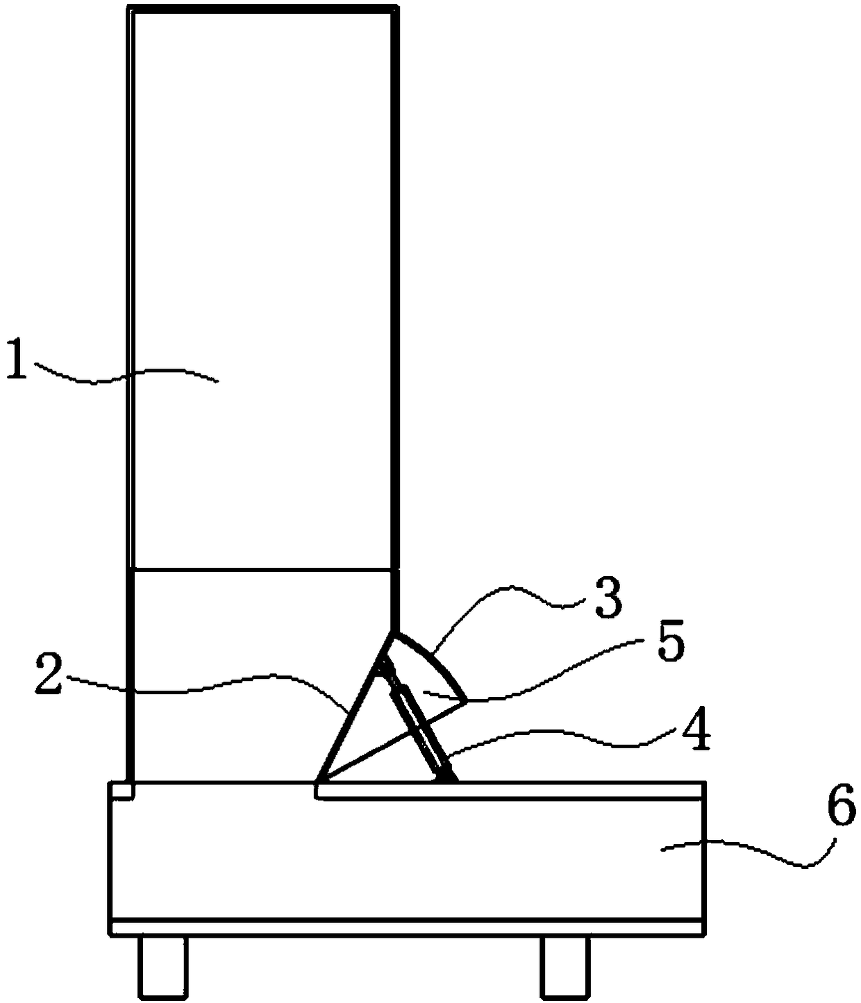
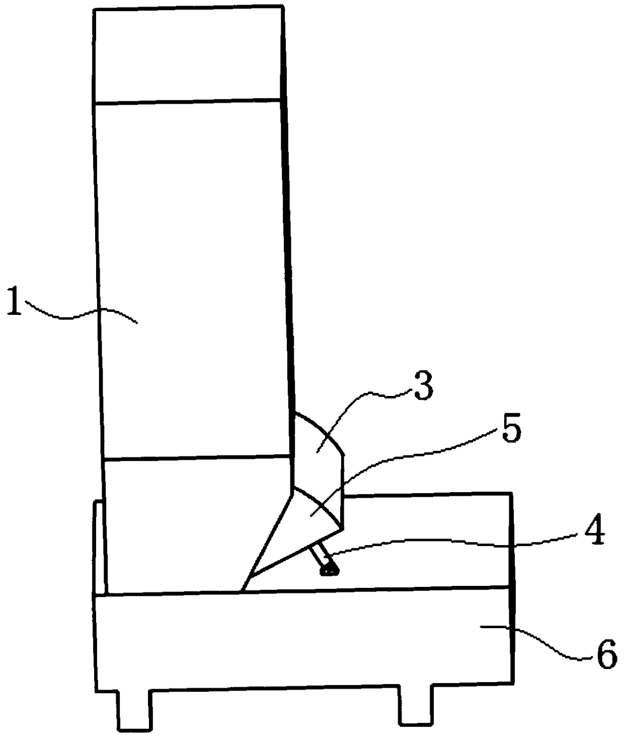
[0017] Figure 1 to Figure 2 A schematic structural view of a blanking mechanism according to a preferred embodiment of the present invention is shown. The blanking mechanism includes a blanking hopper 1 , a pushing plate 2 and an arc-shaped baffle 3 . refer to figure 1 and figure 2 , the upper and lower ends of the blanking hopper 1 are provided with openings, the lower end of the blanking hopper 1 is connected to the ...


PUM


Abstract

The invention discloses a discharging mechanism. The mechanism comprises a discharging hopper, a material pushing plate and an arc-shaped baffle, wherein openings are formed in both upper and lower ends of the discharging hopper, a material pushing port is formed in the lower end of the side wall of the discharging hopper, the lower end of the material pushing plate is hinged to the lower end of the material pushing port in a manner of swinging left and right, the material pushing plate swings through a swinging mechanism, the material pushing plate can swing to the interior of the discharginghopper from the material pushing port, one end of the arc-shaped baffle is connected with the upper end of the material pushing plate, and the other end of the arc-shaped baffle is located outside the discharging hopper; when the material pushing plate swings to the interior of the discharging hopper, the gap between the upper end of the material pushing plate and the upper end of the material pushing port is blocked by the arc-shaped baffle. When the lower end of the discharging hopper is blocked, the material pushing plate can swing towards to the interior of the discharging hopper to squeeze the blocked material downwards, and dredging can be rapidly and conveniently achieved to ensure the normal delivery of materials.

Description

technical field [0001] The invention relates to the field of material conveying, in particular to a blanking mechanism. Background technique [0002] In the process of producing, conveying, processing or other processing of some materials, it is often necessary to introduce the materials into related equipment through the blanking mechanism. For example, in the process of garbage compression, the blanking mechanism is required to guide the garbage into the garbage In the compression chamber of the compression device. The existing blanking mechanism is generally a funnel with a large top and a small bottom. After loading materials from the upper end of the funnel, the materials will freely fall to the relevant equipment below for processing by gravity. For this kind of blanking mechanism that relies on gravity to fall freely, for loose materials that will naturally expand, such as garbage, forage, etc., the lower end of the blanking mechanism is relatively narrow, which is p...

Claims


Application Information

Patent Timeline
IPC IPC(8): B65G65/40B65D88/64
CPCB65D88/64B65G65/40
Inventor 余承旺唐拥军李文嵘林天晓农彦刘艺
Owner 广西玉柴专用汽车有限公司
Why Eureka
Try Eureka