
Scr catalyst channel cleaning and dredging device

An SCR catalyst and catalyst technology, applied in the direction of catalyst regeneration/reactivation, physical/chemical process catalyst, cleaning method using liquid, etc. Collision, solving fragile effects

Inactive Publication Date: 2011-12-21
COUNTRY JIANGSU CATALYST REGENERATION TECH +1
View PDF5 Cites 8 Cited by
  • Summary
  • Abstract
  • Description
  • Claims
  • Application Information

AI Technical Summary

Problems solved by technology

However, the problem with this device is that the current honeycomb catalyst is pressed from powder, and its skeleton is very thin and brittle. unit, and install multiple processing units along the height direction, so that the flue gas passes through the channels of each catalyst to treat the flowing flue gas
However, when cleaning the catalyst, the processing unit can only be placed in the cleaning tank due to the high brittleness of the catalyst. However, during the rotation or swinging process, the catalyst is easily broken and the catalyst cannot be used. Soaking cleans the catalyst in the box, but after the catalyst is blocked, the cleaning liquid cannot circulate, so it is necessary to increase the number and time of soaking, and the cleaning efficiency of the cleaning liquid is very low, which also increases the construction period, increases the construction cost, and increases the work of the workers. quantity

Method used


Image

  • Scr catalyst channel cleaning and dredging device
  • Scr catalyst channel cleaning and dredging device
  • Scr catalyst channel cleaning and dredging device

Examples


Embodiment Construction

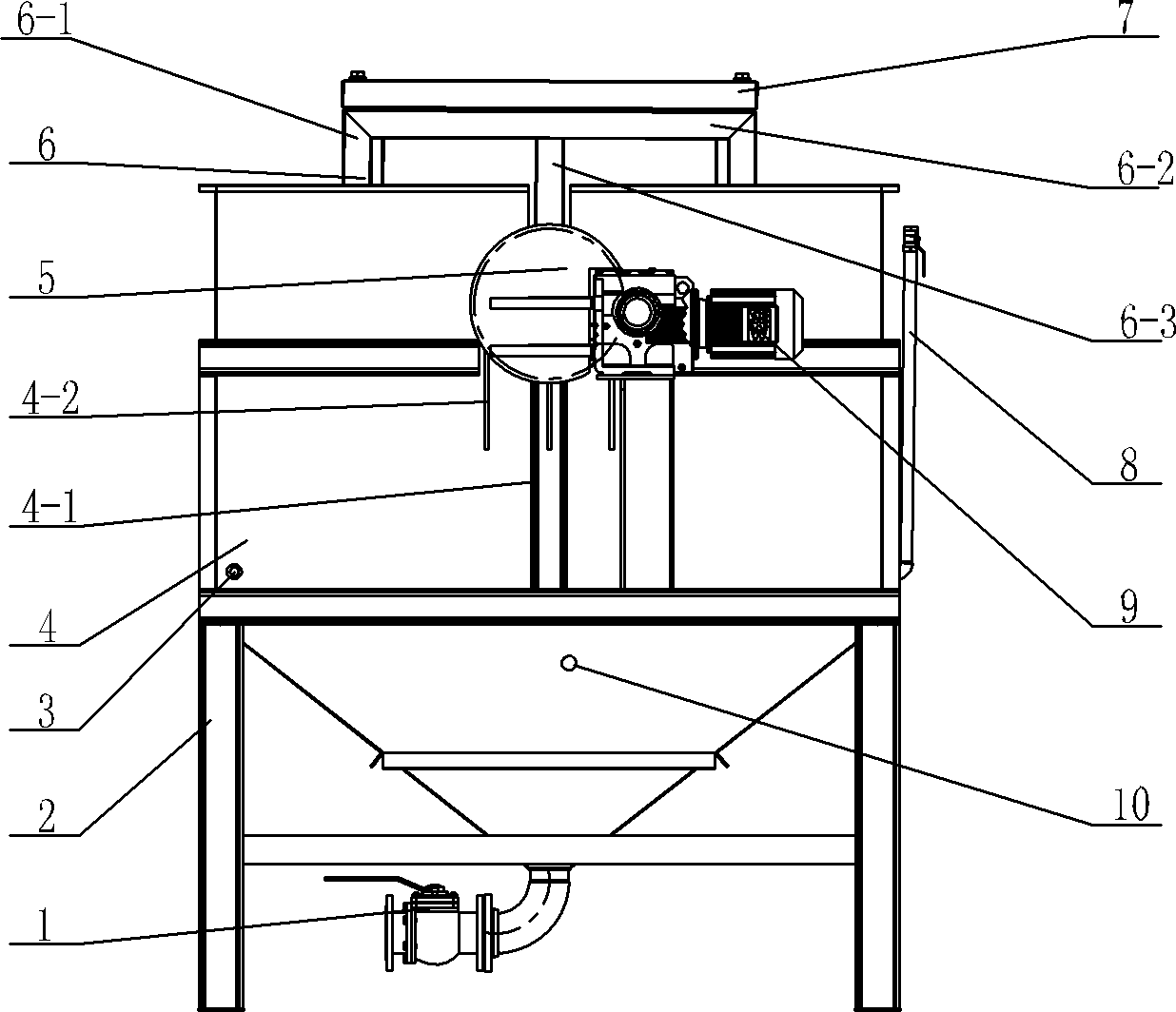
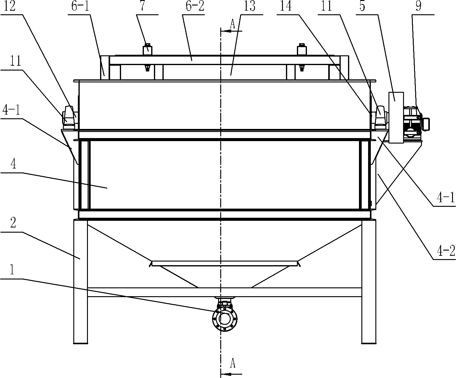
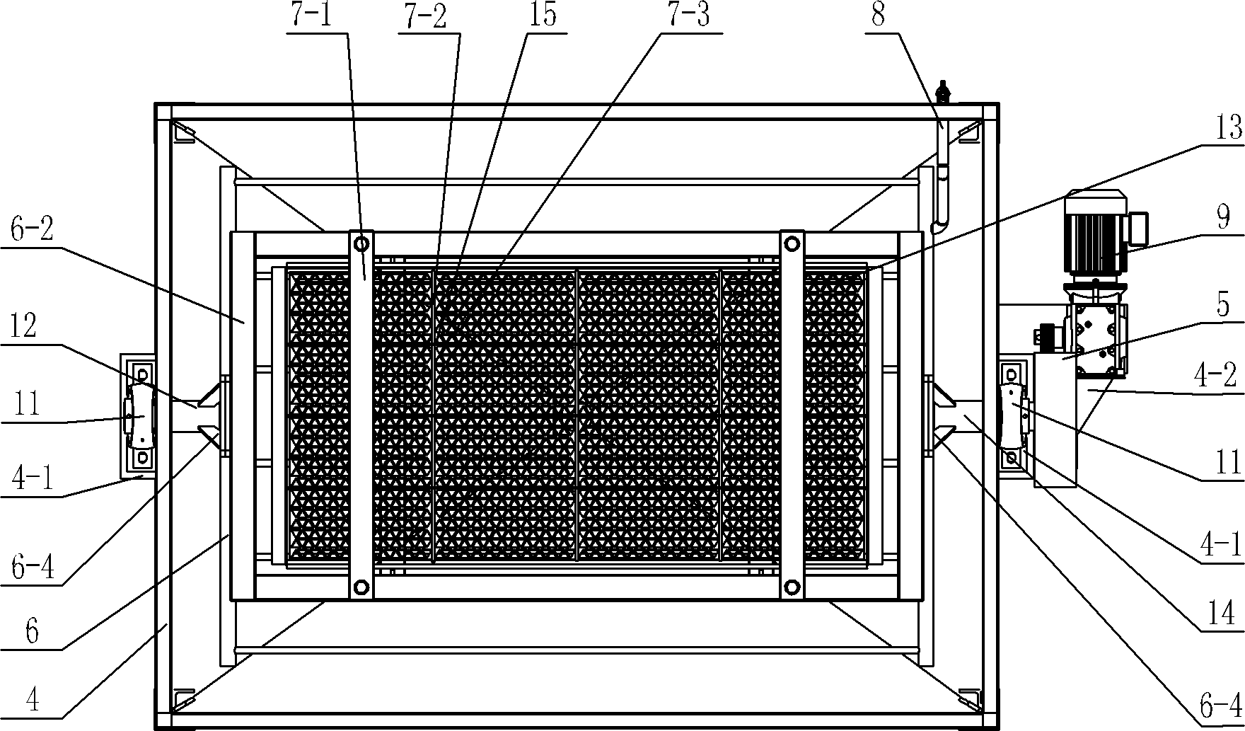
[0019] See Figure 1~3 As shown, the cleaning and dredging device of the SCR catalyst channel of the present invention includes a casing 4 for storing liquid and a supporting mechanism 6 arranged in the casing 4. The bottom of the casing 4 is closed, and the bottom of the casing 4 can be Conical column or prism, the box body 4 is fixed on the frame 2, and the bottom of the box body 4 is provided with a drain valve 1, and the cleaning waste liquid in the box body 4 is discharged through the drain valve 1. The tank 4 is provided with a liquid inlet pipe 8, through which the cleaning and cleaning liquid is added into the tank 4, and a liquid level sensor is installed in the tank 4, and the cleaning and cleaning liquid in the tank 4 can be monitored through the liquid level sensor capacity. Figure 1-7 As shown, the support mechanism 6 of the present invention includes a frame around it and two or more lower support beams 6-5 fixed at the bottom of the frame at intervals. The cat...


PUM


Abstract

The invention relates to a cleaning and dredging device for an SCR (Selective Catalytic Reduction) catalyst pore. A supporting mechanism comprises a frame and lower supporting beams fixed at the bottom of the frame, wherein a drive shaft and a driven shaft which are respectively connected with the frame are arranged on two lateral plates of a box body through bearings, a motor arranged on the boxbody is connected with the drive shaft through a speed reducer, a catalyst unit is vertically arranged in the frame, at least two connecting beams on a top cover are connected with more than two cross beams and more than two longitudinal beams, two sides of the connecting beams are detachably arranged at the top of the frame through fastening members, regulating and limiting mechanisms are arranged on the joints of the top cover and catalysts, regulating members of the regulating and limiting mechanisms are connected with lower supporting plates and upper supporting plates, the lower supporting plates correspond to the joints of all groups of catalysts, cross limiting grooves at the tops of the upper supporting plates are connected with the cross beams and the longitudinal beams, and the lower part of the box body is also provided with a bubbling mechanism. The device provided by the invention has the advantages of reasonable structure, convenience for installation, capability of integrally cleaning the catalyst unit without crushing the catalysts, and capability of improving the cleaning efficiency.

Description

technical field [0001] The invention relates to a device for cleaning and dredging channels of SCR catalysts, belonging to the technical field of catalyst cleaning by selective catalytic reduction method. Background technique [0002] According to the current economic and social development trend, my country's nitrogen oxide emissions will reach 35.4 million tons by 2030. Nitrogen oxide emissions not only make NO 2 Increased concentration can also promote the formation of photochemical smog and fine particles, causing serious air pollution. Coal-fired power plants are one of the main sources of man-made NOx pollution. Controlling NOx emissions in coal-fired power plants is directly related to the overall situation of NOx pollution control. [0003] Among the many denitrification technologies for coal-fired power plants, SCR (Selective Catalytic Reduction) is currently the most widely used, most mature and effective flue gas denitrification technology in the world. Catalys...

Claims


Application Information

Patent Timeline
IPC IPC(8): B01J38/48B08B3/10
Inventor 吴凡袁修江方忠华夏启斌段竞芳
Owner COUNTRY JIANGSU CATALYST REGENERATION TECH
Learn More