An electronic sphygmomanometer for household health care
What is Al technical title?
Al technical title is built by PatSnap Al team. It summarizes the technical point description of the patent document.
A sphygmomanometer, using electronic technology, applied in the direction of cardiac catheterization, etc., can solve the problems of lack of voice broadcast function and unfavorable use by the elderly, and achieve the effect of beautiful and novel appearance, saving equipment investment cost, and reducing input cost
Inactive Publication Date: 2019-01-25
盱眙华新众强智能科技有限公司
View PDF0 Cites 0 Cited by
Summary
Abstract
Description
Claims
Application Information
AI Technical Summary
This helps you quickly interpret patents by identifying the three key elements:
Problems solved by technology
Method used
Benefits of technology
Problems solved by technology
[0003] However, the existing electronic sphygmomanometer lacks the voice broadcast function, which is not conducive to the use of the elderly. Therefore, it is necessary to invent an electronic sphygmomanometer for household health care, which can effectively make up for the shortcomings of the existing electronic sphygmomanometer equipment through the voice broadcast function, and further improve Improve the use efficiency and quality of the electronic sphygmomanometer, and then expand the scope of use of the electronic sphygmomanometer
Method used
Image
Click on the blue label to locate the original text in one second.
Reading with bidirectional positioning of images and text.
Examples
Embodiment Construction
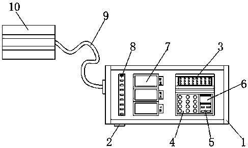
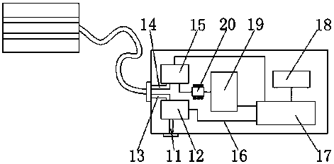
[0015] Such as figure 1 with figure 2 As shown, this specific embodiment adopts the following technical solutions: it includes a sphygmomanometer main body 1, a pressure relief port 2, a speaker hole 3, a control area 4, a switch 5, a time display screen 6, a measurement index display screen 7, and a working state monitoring Light 8, second inflation tube 9, armband 10, second pressure relief tube 11, pressure relief pump 12, first pressure relief tube 13, first inflation tube 14, pressure pump 15, connection line 16, processor 17 , a speaker 18, a display circuit board 19 and an inductive receiving element 20, a pressure relief port 2 is provided on the lower side of the left end of the sphygmomanometer main body 1, a speaker hole 3 is installed on the front side of the right end of the sphygmomanometer main body 1, and a speaker hole 3 is installed on the lower side of the speaker hole 3 Control area 4, a switch 5 and a time display screen 6 are installed on the right side...
PUM
Abstract
The invention discloses an electronic sphygmomanometer for home health care and the invention relates to the technical field of electronic sphygmomanometer. It comprises a sphygmomanometer body, a pressure relief port, a loudspeaker hole, a control area, a switch, a time display, a measurement indicator display, an operating condition monitoring lamp, a second inflation tube; an arm strap, a second relief tube; a pressure relief pump, a first pressure relief pipe, a first inflation pipe, a charging pump, a connection line, a processor, a loudspeaker, a display circuit board, and an inductive receiving element. The pressure relief port is arranged at the lower side of the left end of the sphygmomanometer body, the loudspeaker hole is arranged at the front side of the right end of the sphygmomanometer body, the control area is arranged at the lower side of the loudspeaker hole, and a switch and a time display screen are arranged at the right side of the control area. The invention has the advantages of scientific and reasonable structural design, beautiful and novel appearance, convenient operation and use by users, low investment cost, saving funds, improving economic efficiency, reducing operation error rate, realizing high efficiency, energy conservation and environmental protection, and being beneficial to wide-range popularization and use.
Description
Technical field: [0001] The invention relates to an electronic sphygmomanometer for household health care, belonging to the technical field of electronic sphygmomanometers. Background technique: [0002] Electronic sphygmomanometer is a medical device that uses modern electronic technology and the principle of indirect blood pressure measurement to measure blood pressure. Electronic sphygmomanometer has become the main tool for self-testing blood pressure at home, and is also increasingly used in hospitals and other medical institutions. [0003] However, the existing electronic sphygmomanometer lacks the voice broadcast function, which is not conducive to the use of the elderly. Therefore, it is necessary to invent an electronic sphygmomanometer for household health care, which can effectively make up for the shortcomings of the existing electronic sphygmomanometer equipment through the voice broadcast function, and further improve The use efficiency and quality of the elec...
Claims
Application Information
Patent Timeline
Application Date:The date an application was filed.
Publication Date:The date a patent or application was officially published.
First Publication Date:The earliest publication date of a patent with the same application number.
Issue Date:Publication date of the patent grant document.
PCT Entry Date:The Entry date of PCT National Phase.
Estimated Expiry Date:The statutory expiry date of a patent right according to the Patent Law, and it is the longest term of protection that the patent right can achieve without the termination of the patent right due to other reasons(Term extension factor has been taken into account ).
Invalid Date:Actual expiry date is based on effective date or publication date of legal transaction data of invalid patent.