Movable massage backrest function conversion mechanism

A conversion mechanism and backrest technology, applied in massage auxiliary products, roller massage, kneading massage equipment, etc., can solve the problems of space waste, single function, and inability to form rigid support, so as to improve popularization and avoid space waste Effect

Pending Publication Date: 2019-01-25
WENZHOU ZHEYIGE TECH CO LTD
View PDF0 Cites 5 Cited by
  • Summary
  • Abstract
  • Description
  • Claims
  • Application Information

AI Technical Summary

Problems solved by technology

[0003] Although the massage chair can achieve the effect and purpose of massage, the massage chairs on the market usually adopt the walking structure of the massage movement. There is a window hole in the backrest support frame for the movement of the massage movement. This part is a hollow structure. The back of the human body is supported by the outermost decorative layer and kneading layer of the massage chair. Strictly speaking, these two layers cannot form a rigid support because the massage components need to walk and massage, and the human back cannot get it. strong support
[0004] From the above, it can be concluded that the existing massage chairs are not suitable for use as ordinary seat chairs, because their functions are single, and because there is no rigid support, they can only be used when massaging. The chair will make the back of the human body very uncomfortable, it is very "diaphragmatic", and its overall volume is too large, vacant will cause a lot of space waste and inconvenience, how to convert the massage chair into a seat when not in use The chair is the problem we have to solve now

Method used


Image

  • Movable massage backrest function conversion mechanism
  • Movable massage backrest function conversion mechanism
  • Movable massage backrest function conversion mechanism

Examples


Embodiment 1

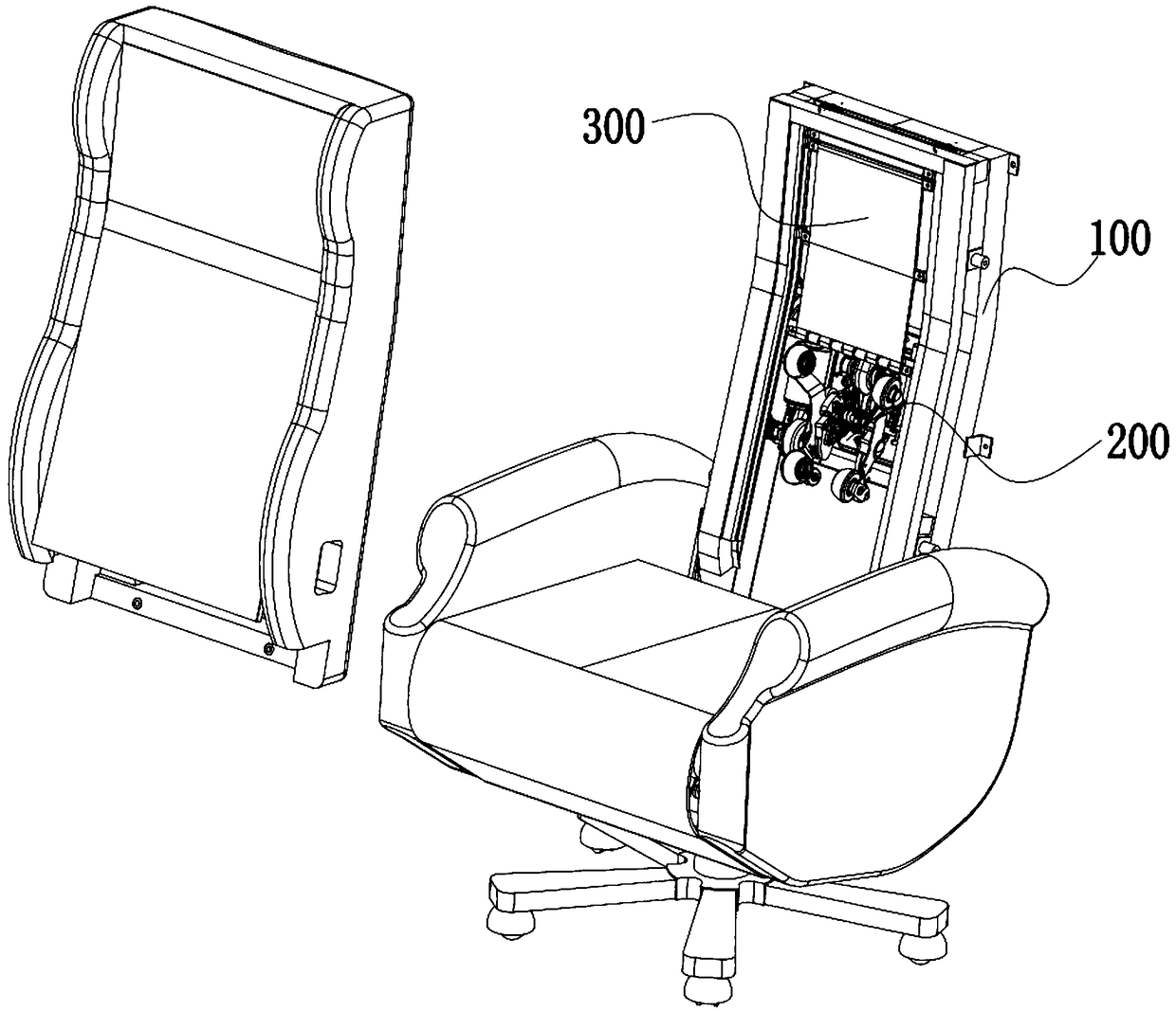
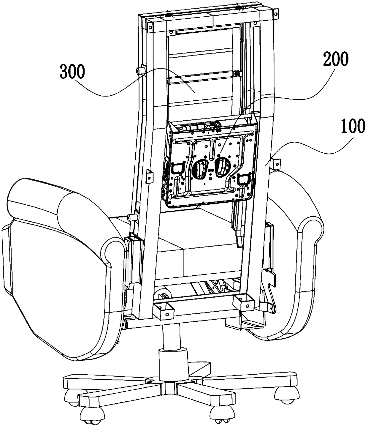
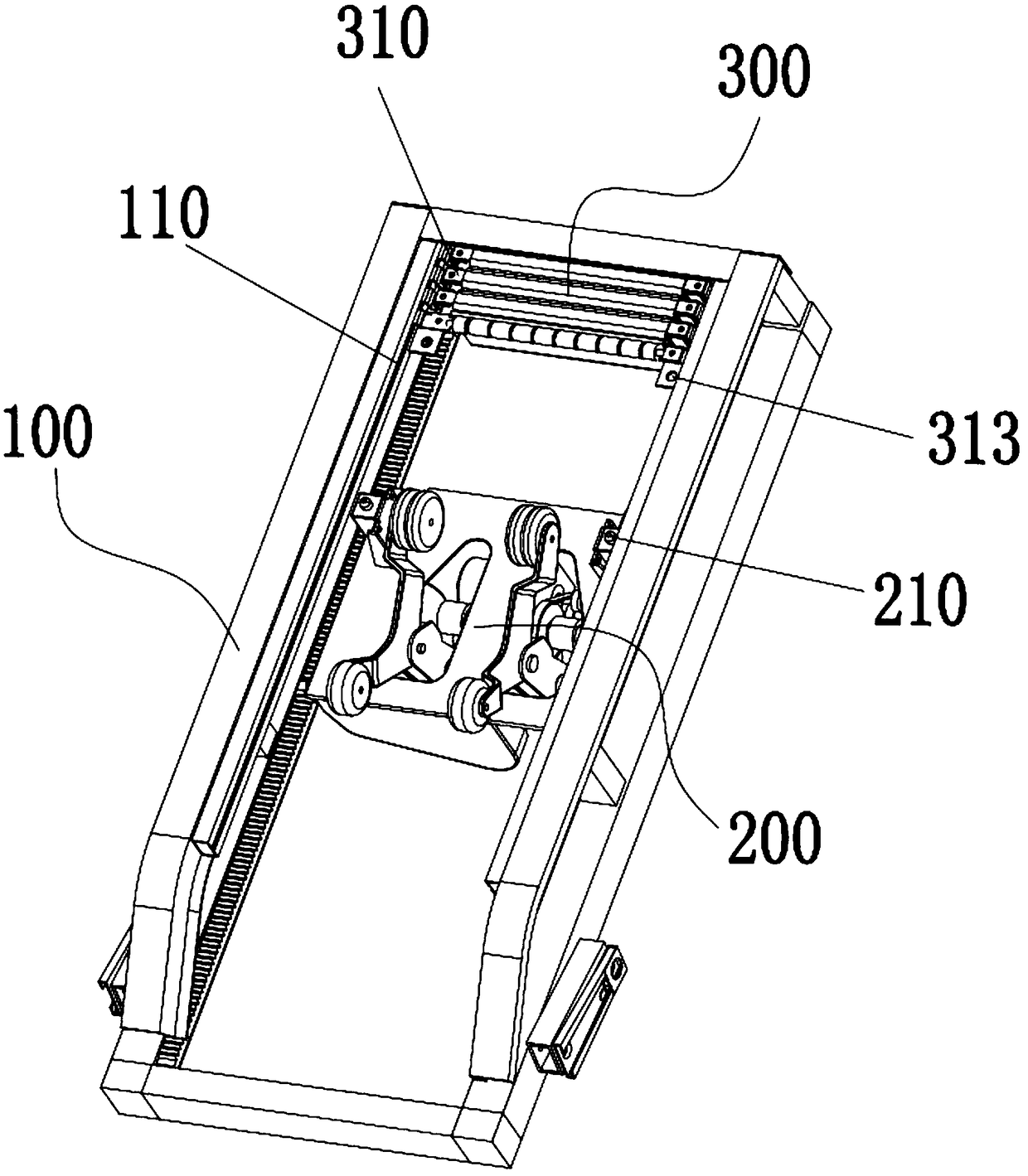
[0052] Embodiment 1; as Figure 1-Figure 7As shown, a function conversion mechanism of a movable massage backrest includes a leaning object body, and the leaning object body includes a backrest support frame 100 and a massage assembly 200 on the back of a human body. The massage assembly 200 has a walking path in the backrest support frame 100, and the backrest support The frame 100 is provided with a movable backrest mechanism 300 that supports the back of the human body. The backrest mechanism 300 at least partially covers the walking path of the massage assembly 200. In this patent, a movable backrest mechanism that provides support for the back of the human body is provided at the hollowed-out window position of the backrest support frame 100. 300. Massage components 200 are collectively referred to as components that provide human back massage such as massage cores, guide rails, fixing frames, massage wheels, or massage bumps. This is a mature technology on the market, at ...

Embodiment 2

[0061] Embodiment 2; as Figure 8-Figure 12 As shown, the difference between this embodiment and Embodiment 1 is that this embodiment is a backrest mechanism 300 of a telescopic structure, and the backrest mechanism 300 includes several backboards 330, and adjacent backboards 330 are telescopically matched, and the backboards 330 and The support rods 310 are fixedly connected, and the backboard 330 realizes mutual conversion between the extended state and the contracted state of the backrest mechanism 300 through the expansion and closing of several support rods 310 .

[0062] The backing boards 330 are nested with each other, one side of the adjacent backing boards 330 is provided with a stopper 331 for stretching the backing boards 330, and the other side of the adjacent backing boards 330 is provided with a stopper for shrinking the backing boards 330. Connection 332.

[0063] The backing plate 330 realizes socketing through successively increasing or decreasing sections, ...

Embodiment 3

[0064] Embodiment 3; as Figure 13-Figure 16 As shown, the difference between this embodiment and Embodiments 1 and 2 is that this embodiment is a backrest mechanism 300 with a roller shutter structure. The rod 310 is connected, including a reel 350 for winding and unwinding the support rod 310. The second support member 340 realizes the transition between the extended state and the contracted state of the backrest mechanism 300 through the winding and unwinding of several support rods 310. convert each other.

[0065] The reel 350 is arranged at one end of the guide groove 110, and the reel 350 and the guide groove 110 are respectively provided with a rebound mechanism and a limit mechanism. The rebound mechanism is such as a coil spring. The extension of the backrest mechanism 300 is the contraction of the backrest mechanism 300 when it moves toward the direction of the roll 350 .


PUM


Abstract

The invention relates to a function conversion mechanism, in particular to a function conversion mechanism for providing a movable backrest support to a massage chair or a massage table, includes a leaning body, the leaning body include a backrest support frame and a massage assembly for that back of a human body, the function conversion mechanism is characterized in that the massage assembly hasa travel path within that backrest support frame, the backrest support frame is provided with a movable backrest mechanism supporting the back of a human body, the backrest mechanism at least partially covers the travel path of the massage assembly, a movable leaning plate is additionally arranged in the back support frame of the massage chair, the movable backrest plate provides a rigid support for the back of the human body, and can be converted into a common seat chair for use without using the massage function, thereby avoiding space waste caused by the massage chair. Especially for the universal seat chair, the movable backrest support mechanism is added, which greatly improves the popularization and application of the seat chair massage function.

Description

technical field [0001] The utility model relates to a function conversion mechanism, in particular to a function conversion mechanism which provides movable back support for a massage chair or a massage bed. Background technique [0002] With the improvement of the quality of life, luxury consumer goods such as electric massage chairs have entered thousands of households. With the influx of e-commerce, shared electric massage chairs have been placed in many large shopping malls, cinemas and other public places. In addition, it can relax muscles and reduce fatigue. [0003] Although the massage chair can achieve the effect and purpose of massage, the massage chairs on the market usually adopt the walking structure of the massage movement. There is a window hole in the backrest support frame for the movement of the massage movement. This part is a hollow structure. The back of the human body is supported by the outermost decorative layer and kneading layer of the massage chai...

Claims


Application Information

Patent Timeline
Patent Type & Authority Applications(China)
IPC IPC(8): A61H15/00A47C7/40
CPCA47C7/40A61H1/001A61H7/007A61H15/0078A61H2015/0021A61H2015/0028A61H2201/0149A61H2205/081
Inventor 杨柏清
Owner WENZHOU ZHEYIGE TECH CO LTD
Why Eureka
Try Eureka