Quick-change type fan-shaped soft claw

A quick-change, soft-claw technology, applied in the field of machining, can solve the problems of not being universal, wasting manpower, easy to produce stress and deformation, etc., achieving the effect of good universal type, fast and convenient clamping, and low manufacturing cost.

Inactive Publication Date: 2019-01-25
THE RES INST FOR SPECIAL STRUCTURES OF AERONAUTICAL COMPOSITE AVIC
View PDF3 Cites 2 Cited by
  • Summary
  • Abstract
  • Description
  • Claims
  • Application Information

AI Technical Summary

Problems solved by technology

The advantage of this kind of soft claw is: six points are used to hold the part in the tangent plane perpendicular to the axis, and the part is clamped reliably; When the shape error of the outer circle of the part positioning is large, it will affect the accuracy of the center positioning of the soft jaw; (2) the six clamping points are basically point contacts, which are easy to damage the outer circle of the part positioning
The disadvantage is: the clamping reliability is not as good as the first solution
Its disadvantages are: the actual contact area is too small, and when the workpiece belongs to the field of thin-walled parts, it is easy to produce stress deformation during processing
[0006] From the usual design method of soft jaws in the machinery industry, it can be seen that no matter what design scheme is adopted, on the one hand, when the workpiece is clamped by the soft jaws, it belongs to three-point or six-point clamping of the workpiece, although the soft jaws can play a role in the workpiece. Protective effect, but when the workpiece belongs to the field of thin-walled parts, it is easy to produce stress deformation during processing
On the other hand, for workpieces with different diameters, soft jaws with different diameters must be equipped. If it is not universal, different soft jaws must be installed and unloaded when processing different parts. More troublesome, waste of manpower

Method used


Image

  • Quick-change type fan-shaped soft claw
  • Quick-change type fan-shaped soft claw
  • Quick-change type fan-shaped soft claw

Examples


Embodiment Construction

[0018] The specific embodiments of the present invention will be further described below in conjunction with the accompanying drawings.

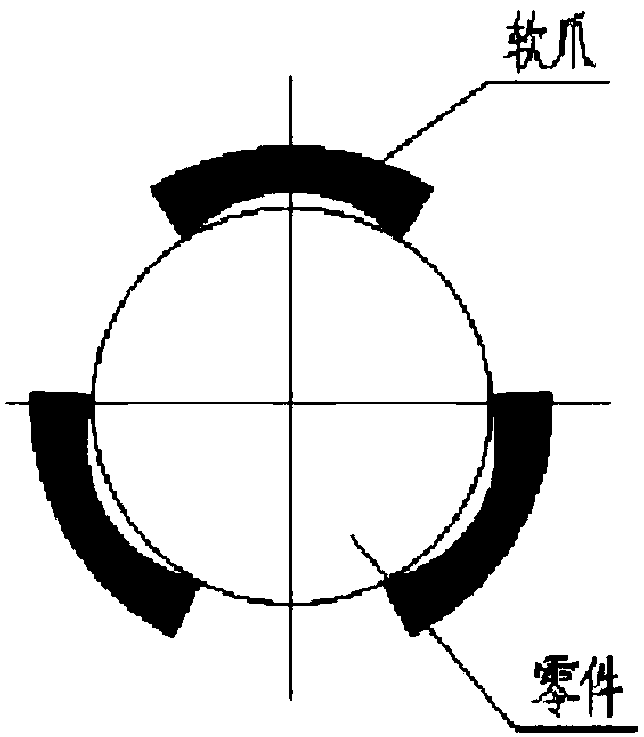
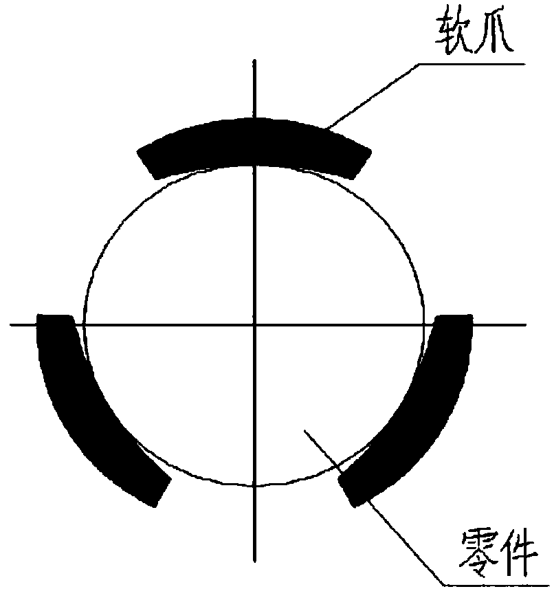
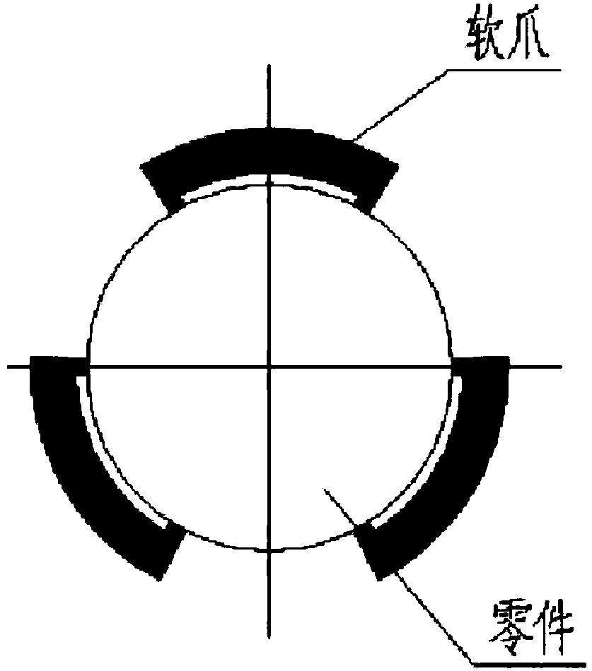
[0019] Because the jaws of the three-jaw chuck have a detachable function. For the multi-variety and small-batch workpieces in the workshop, a machine tool and a three-jaw chuck can be used to design different replaceable soft jaws. When processing different products, the soft jaws can be quickly replaced. At the same time, the designed soft jaws have a large sector of contact, and are also suitable for processing workpieces with insufficient rigidity.

[0020] see Figure 4 , Figure 5 , the device of the present invention is a quick-change fan-shaped soft claw, and its components are a claw 1, an upper connector 2, a self-made soft claw 3, and a connecting screw 4. Among them, the jaw 1 is modified from the traditional three jaws, and the part that can be connected with the flat thread of the chuck is reserved. After the upper connectin...


PUM


Abstract

The invention belongs to the technical field of machining, and relates to a quick-change type fan-shaped soft claw. The fan-shaped soft claw comprises a clamping claw, an upper connection piece, a home-made soft claw body and connection bolts, wherein the clamping claw comprises a section thread on the left side and a dovetail groove in the right side, the section thread is cooperatively connectedwith a chuck plane thread, and the clamping claw is cooperatively and fixedly connected with the upper connection piece through the dovetail groove; after the clamping claw cooperates with the upperconnection piece, a welding joint is firmly welded; threaded holes are formed in the right side of the upper connection piece; threaded holes are formed in the home-made soft claw body and are consistent with the threaded holes in the upper connection piece; the connection bolts penetrate through the threaded holes in the home-made soft claw body and the upper connection piece, so that the upper connection piece is fixedly connected with the home-made soft claw body; the home-made soft claw body is custom-made according to the diameter of a machined workpiece, and the inner diameter of the home-made soft claw body is equal to the outer diameter of the machined workpiece. When workpieces of different specifications are machined by using the quick-change type fan-shaped soft claw, the soft claw body can be quickly replaced.

Description

technical field [0001] The invention belongs to the technical field of machining, and relates to a quick-change sector-shaped soft claw. Background technique [0002] The application of soft claws in machining is more and more extensive. However, when it comes to how to design and manufacture soft claws, there are three main design schemes of soft claws in the machining industry. [0003] Option 1: The inner circle size of the claw clamping part is 0.05-0.08mm smaller than the smallest entity of the part positioning size, and the action width of each claw is 1 / 8-1 / 6 of the part positioning outer circle circumference (see Figure 1 ). The advantage of this kind of soft claw is: six points are used to hold the part in the tangent plane perpendicular to the axis, and the part is clamped reliably; When the shape error of the part positioning outer circle is large, it will affect the accuracy of the center positioning of the soft jaw; (2) the six clamping points are basically po...

Claims


Application Information

Patent Timeline
Patent Type & Authority Applications(China)
IPC IPC(8): B23B31/10B23B31/103
CPCB23B31/10B23B31/102B23B31/103
Inventor 董光亮肖瑞利
Owner THE RES INST FOR SPECIAL STRUCTURES OF AERONAUTICAL COMPOSITE AVIC
Why Eureka
Try Eureka