Steel tube storage vehicle

A steel pipe and support plate technology, which is applied in the field of steel pipe stacking or retrieval, can solve the problems of hurting others, hidden dangers, and difficulty in taking out construction steel pipes, so as to achieve the effect of convenient movement.

Inactive Publication Date: 2019-01-25
何召焓
View PDF0 Cites 0 Cited by
  • Summary
  • Abstract
  • Description
  • Claims
  • Application Information

AI Technical Summary

Problems solved by technology

[0002] At present, in the field of construction, construction steel pipes are commonly used building material consumables, especially in the construction environment that requires a large number of scaffolding installations, it is necessary to use a large number of construction steel pipes; Although there is also a place for uniform stacking, these stacked construction steel pipes are inconvenient to use and there are certain safety hazards, especially when workers take construction steel pipes, once some accidents occur, these buildings, which are themselves cylindrical structures Steel pipes are prone to rollover and collapse accidents, and construction steel pipes at high places are easy to roll over and fall and hurt others
In order to avoid accidents caused by the stacked construction steel pipes rolling over and falling, the construction steel pipes can be stacked in a larger stacker, but when one or more construction steel pipes in the stacker need to be taken, the construction steel pipes in the stacker should not be used. Because of the large accumulation, it is easy to cause blockage, which makes it difficult to take out the construction steel pipes in the stacked truck

Method used


Image

  • Steel tube storage vehicle
  • Steel tube storage vehicle
  • Steel tube storage vehicle

Examples


Embodiment Construction

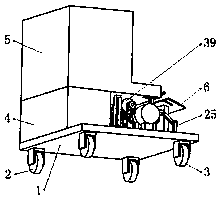
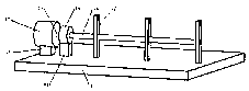
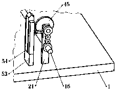
[0044] Such as figure 1 As shown, it includes a base 1, a directional wheel 2, a steering wheel 3, a stacking shell 5 installed on the base 1 through a total support block 4, such as figure 2 As shown, the inclined plate 6, the baffle plate 14, the output shaft 16 installed on the base 1 through two symmetrically distributed first support plates 7, such as Figure 10 As shown, the motor 17 installed on the base 1 by the first support block 18, such as Figure 10 As shown, the reducer 19, the input shaft 22, the second support plate 21, the actuator 25, and the anti-blocking mechanism 39 installed on the base 1 through the second support block 20, such as figure 1 As shown, two directional wheels 2 are symmetrically installed at one end of the lower surface of the base 1, and two steering wheels 3 are symmetrically installed at the other end; as figure 2 , 4 As shown, there is a discharge case 8 on the stacking case 5, a stacking groove 9 is arranged in the stacking case 5...


PUM


Abstract

The invention belongs to the technical field of steel tube stacking or taking, and particularly relates to a steel tube storage vehicle which comprises a base, a stacking shell, an input shaft, a motor, an actuating mechanism and an anti-blocking mechanism. After the motor is started, an output shaft slowly rotates and transfers power, so that the actuating mechanism acts, steel tubes in a discharging shell can be lifted out one by one by action of the actuating mechanism, the anti-blocking mechanism acts after the output shaft transfers power, and blocking of the steel tubes can be relieved by action of the anti-blocking mechanism. The steel tubes can be orderly discharged from the discharging shell, and a large number of steel tubes can be prevented from rolling out of the discharging shell at a stroke and further causing potential hazards to workers. The steel tube storage vehicle is simple in structure, a large number of building steel tubes can be conveniently stacked, or the required building steel tubes can be orderly taken, and good use effects are achieved.

Description

technical field [0001] The invention belongs to the technical field of stacking or taking steel pipes, and in particular relates to a steel pipe storage vehicle. Background technique [0002] At present, in the field of construction, construction steel pipes are commonly used building material consumables, especially in the construction environment that requires a large number of scaffolding installations, it is necessary to use a large number of construction steel pipes; Although there is also a place for uniform stacking, these stacked construction steel pipes are inconvenient to use and there are certain safety hazards, especially when workers take construction steel pipes, once some accidents occur, these buildings, which are themselves cylindrical structures Steel pipes are prone to rollover and collapse accidents, and construction steel pipes at high places are easy to roll over and fall and hurt others. In order to avoid accidents caused by the stacked construction s...

Claims


Application Information

Patent Timeline
Patent Type & Authority Applications(China)
IPC IPC(8): B25H3/00B25H5/00
CPCB25H3/00B25H5/00
Inventor 陆映红
Owner 何召焓
Why Eureka
Try Eureka