Gas-liquid separator

A gas-liquid separator and outlet pipe technology, used in refrigeration and liquefaction, refrigeration components, refrigerators, etc., can solve problems such as difficulty in oil return, unavailability of compressors, and impact on life, and achieve good oil return effect without causing wasteful effect

Pending Publication Date: 2019-01-25
GUANGDONG NEW ENERGY TECH DEV
View PDF0 Cites 3 Cited by
  • Summary
  • Abstract
  • Description
  • Claims
  • Application Information

AI Technical Summary

Problems solved by technology

[0002] According to the market research information feedback, the existing gas-liquid separator generally has the problem of difficult oil return in the heat pump system, and the compressor cannot get enough lubricating oil, which will affect its life during use.

Method used


Image

  • Gas-liquid separator
  • Gas-liquid separator

Examples


Embodiment Construction

[0012] In order to make the object, technical solution and advantages of the present invention clearer, the present invention will be further described in detail below by taking an air-conditioning system as an example, with reference to the accompanying drawings and embodiments. It should be understood that the specific embodiments described here are only used to explain the present invention, not to limit the present invention.

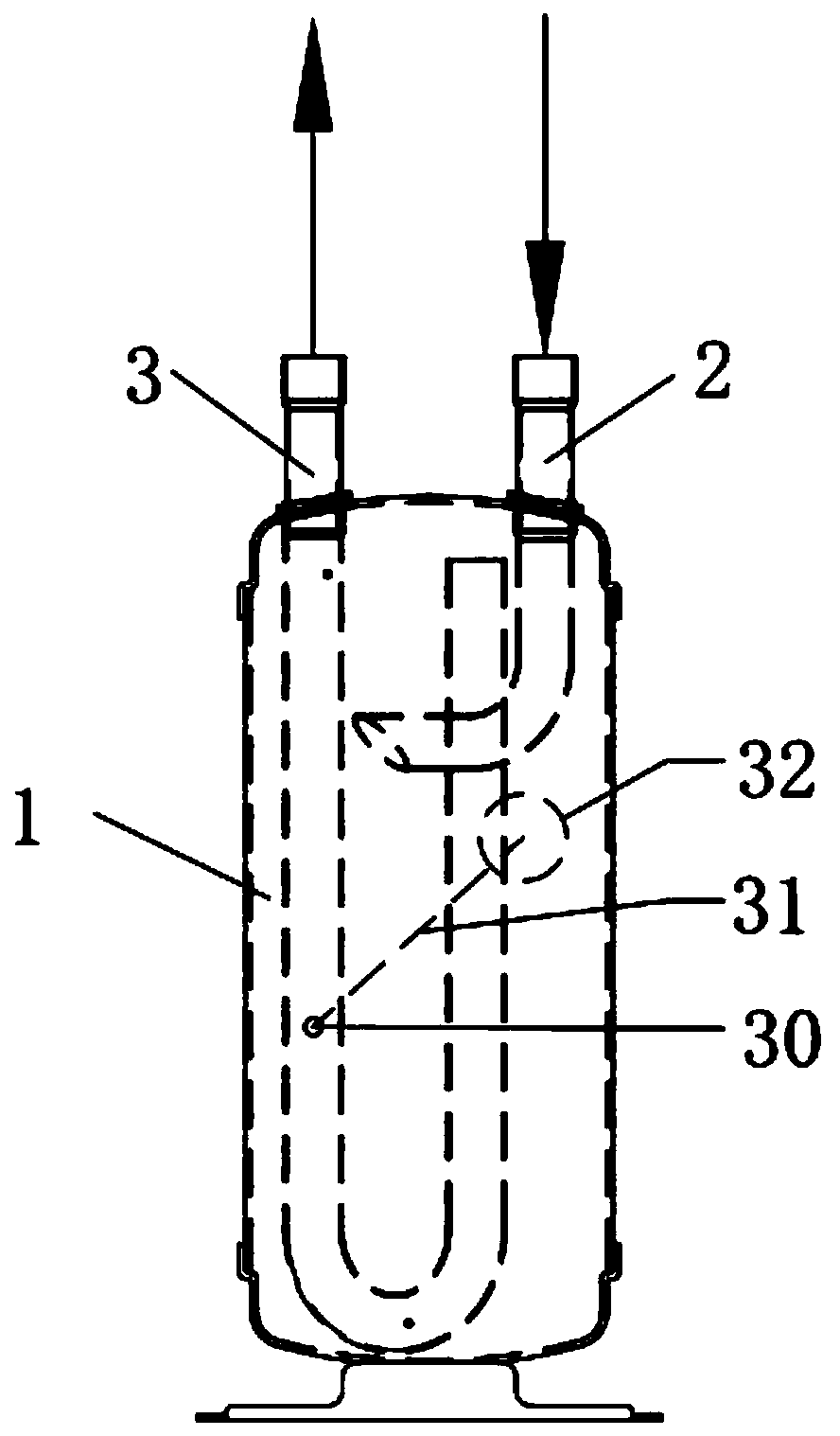
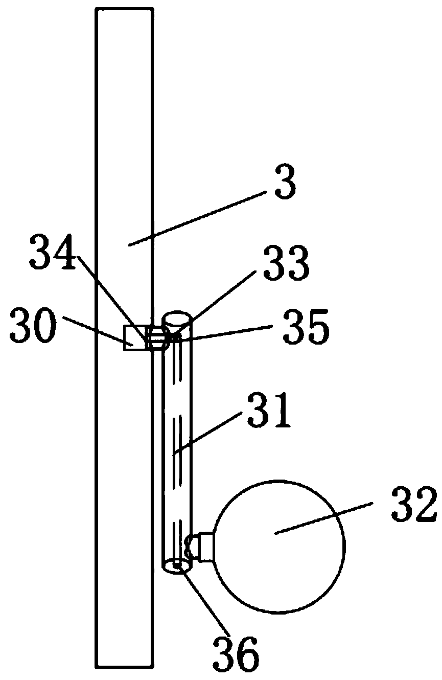
[0013] Such as Figure 1-2 As shown, the gas-liquid separator includes a tank body 1, the tank body 1 is provided with an inlet pipe 2 and an outlet pipe 3, the gas-liquid mixture enters the tank body 1 through the inlet pipe 2, and the outlet pipe 3 Connected with sequentially arranged struts 30, connecting rods 31 and oil return floats 32 that can float on the liquid surface, the struts 30 are installed on the pipeline of the outlet pipe 3, and the struts 30 are equipped with pipeline, the pipeline includes a pole inlet pipeline 33 and a pole out...


PUM


Abstract

The invention belongs to the technical field of heat pump systems, and particularly relates to a gas-liquid separator which comprises a tank. An inlet pipe and an outlet pipe are arranged in the tank,gas-liquid mixture enters the tank through the inlet pipe, a supporting rod, a connecting rod and an oil return floating ball are connected onto the outlet pipe and sequentially arranged, and the oilreturn floating ball can float on the surface of liquid.

Description

technical field [0001] The invention belongs to the technical field of heat pump systems, in particular to a gas-liquid separator. Background technique [0002] According to market research information feedback, existing gas-liquid separators generally have difficulty in oil return in heat pump systems. If the compressor cannot get enough lubricating oil, its life will be affected during use. Contents of the invention [0003] In order to overcome the deficiencies of the prior art, the object of the present invention is to provide a gas-liquid separator that is easy to return oil. [0004] In order to solve the problems of the technologies described above, the technical solution adopted by the gas-liquid separator of the present invention is: [0005] The gas-liquid separator includes a tank body, the tank body is provided with an inlet pipe and an outlet pipe, the gas-liquid mixture enters the tank body through the inlet pipe, and the outlet pipe is connected with sequen...

Claims


Application Information

Patent Timeline
Patent Type & Authority Applications(China)
IPC IPC(8): F25B43/02
CPCF25B43/02F25B2500/16
Inventor 赵密升李明李建国张娟萍
Owner GUANGDONG NEW ENERGY TECH DEV
Why Eureka
Try Eureka