Rod bundle channel visualization experiment body suitable for heating boiling conditions

A technology of rod bundle channel and body, which is applied in the field of rod bundle channel visualization experiment body, can solve the problem of not being able to obtain the details of fuel assembly flow and heat transfer behavior, and achieve the effects of improving the visualization range, low price, and easy processing

Pending Publication Date: 2019-01-25
HARBIN ENG UNIV
View PDF0 Cites 4 Cited by
  • Summary
  • Abstract
  • Description
  • Claims
  • Application Information

AI Technical Summary

Problems solved by technology

However, due to the complex structure of the fuel assembly and the study of its internal flow and heat transfer behavior, scholars at home and abroad often use traditional thermocouples to measure the wall temperature of the rod bundle to predict the flow and heat transfer behavior in the rod bundle channel, and the measurement of the thermocouple can only Measuring the temperature of a single point or some points cannot obtain the detailed flow and heat transfer behavior in the fuel assembly, and the arrangement of thermocouples will inevitably have a certain impact on the internal behavior of the real fuel assembly, which will eventually lead to engineering problems. The real heat and mass transfer process in the component is still

Method used


Image

  • Rod bundle channel visualization experiment body suitable for heating boiling conditions
  • Rod bundle channel visualization experiment body suitable for heating boiling conditions
  • Rod bundle channel visualization experiment body suitable for heating boiling conditions

Examples


Embodiment Construction

[0024] The present invention will be further described in detail below in conjunction with the accompanying drawings and specific embodiments.

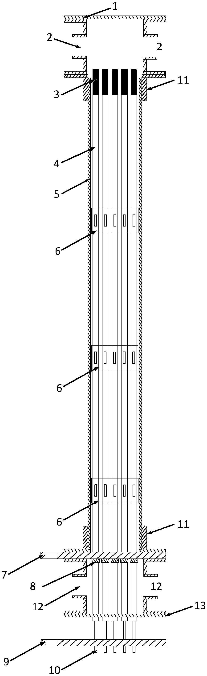
[0025] The present invention provides a rod bundle channel visualization experiment body for heating and boiling conditions, which realizes the perfect combination of traditional heat transfer characteristic measurement and visualized advanced measurement means, and can be used for the temperature measurement of the inner wall surface of the rod bundle channel and the flow in the rod bundle channel Visual measurement of heat transfer behavior; the present invention has a rod bundle channel visualization experiment body, which has a simple structure, low price, and a wide range of research conditions covering single-phase and boiling two-phase, and can be used to measure flow and heat transfer characteristics of rod bundle channels under complex conditions.

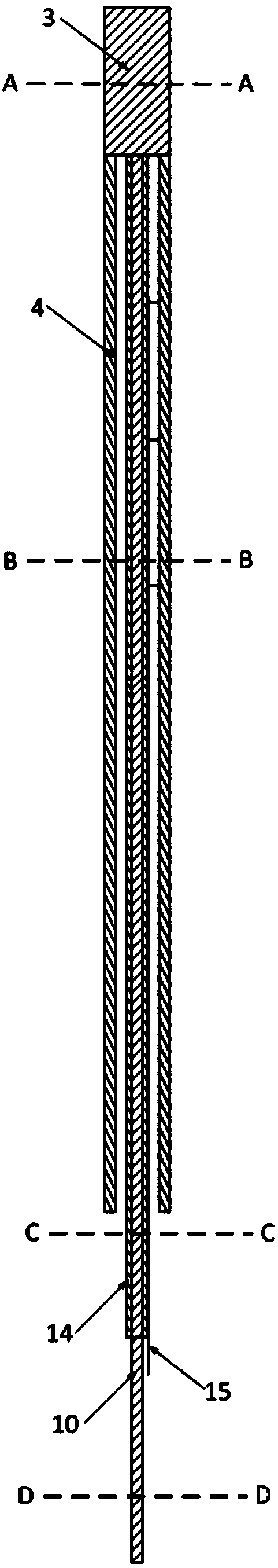
[0026] The experimental body of the present invention mainly includes a square...


PUM


Abstract

The invention provides a rod bundle channel visualization experiment body suitable for heating boiling conditions. The experiment body comprises a square quartz channel, an outlet and an inlet respectively disposed at the upper end and the lower end of the square quartz channel and a simulated fuel rod bundle disposed in the square quartz channel. The lower end of the simulated fuel rod bundle isconnected to the square quartz channel through a sealing flange. The experiment body is further provided with a positive conductive copper bar and a negative conductive copper bar, and the positive conductive copper bar is disposed at the upper end of the inlet of the body. The simulated fuel rod bundle includes a connecting copper head and a conductive copper rod and a stainless steel tube whichare arranged at the lower end of the connecting copper head. The conductive copper rod is disposed inside the stainless steel tube, and the outer surface of the conductive copper rod is provided withan insulating tube. The stainless steel tube is connected with the positive conductive copper bar, and the conductive copper rod is connected with the negative conductive copper bar. The experiment body solves the problem that the traditional wall temperature measurement method and a visualization experiment cannot be combined, can achieve measurement study of an inner flow field temperature fieldof the rod bundle channel under high temperature and two-phase conditions, and has the advantages of simple design and low cost.

Description

technical field [0001] The invention relates to a rod bundle channel visualization experiment body, in particular to a rod bundle channel visualization experiment body suitable for heating and boiling conditions, and belongs to the fields of fluid mechanics, heat transfer, reactor thermal hydraulics, nuclear safety and the like. Background technique [0002] The PWR core fuel assembly is an atypical rod bundle channel structure, and the fuel assembly is also equipped with a positioning grid, which leads to a more complicated fluid circulation structure in the fuel assembly, and further promotes the complex heat and mass transfer process in the fuel unit. for complex. During the normal operation of the reactor, the research on the steady-state flow heat transfer engineering in the bundle channel is very important for the economical efficiency of the reactor. Under accident conditions, especially under flow transient conditions, the flow in the bundle channel is prone to heat ...

Claims


Application Information

Patent Timeline
IPC IPC(8): G21C17/00
CPCG21C17/00Y02E30/30
Inventor 谭思超李兴祁沛垚孟涛程坤何宇豪郝思佳
Owner HARBIN ENG UNIV
Why Eureka
Try Eureka