Start-up and excitation system of gas turbine generator set, method
A technology for gas turbines and generator sets, which is applied to the control of generators, control of generators through magnetic field changes, and control systems. cost effect
- Summary
- Abstract
- Description
- Claims
- Application Information
AI Technical Summary
Problems solved by technology
Method used
Image

Examples
Embodiment Construction
[0028] It should be noted that, in the case of no conflict, the embodiments in the present application and the features in the embodiments can be combined with each other. The present invention will be described in detail below with reference to the accompanying drawings and examples.
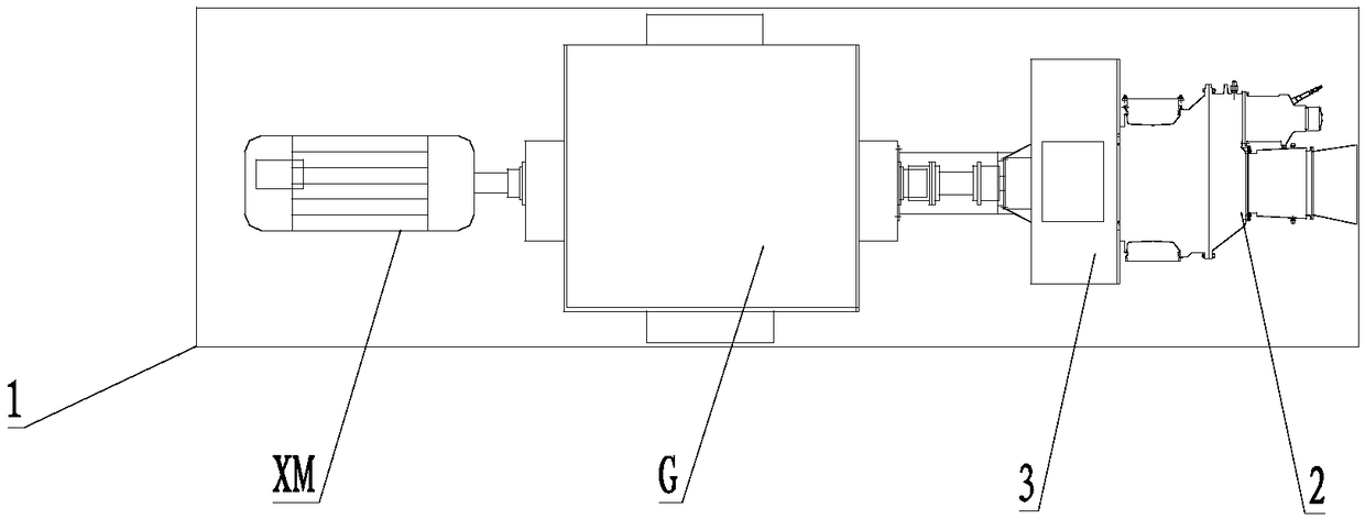
[0029] refer to figure 1 , The gas turbine generator set of the present invention is a small gas turbine generator set, which as a whole includes a gas turbine 2 arranged on a base 1, a speed reducer 3, a generator G and a separately excited DC motor XM. In this preferred embodiment, the generator G is a brushed generator, and the separately excited DC motor XM is a standard separately excited DC motor. The gas turbine 2 is coaxially installed and connected to the generator G through a speed reducer 3 . Separately excited DC motor XM is coaxially installed with generator G, and the rated speed is the same.
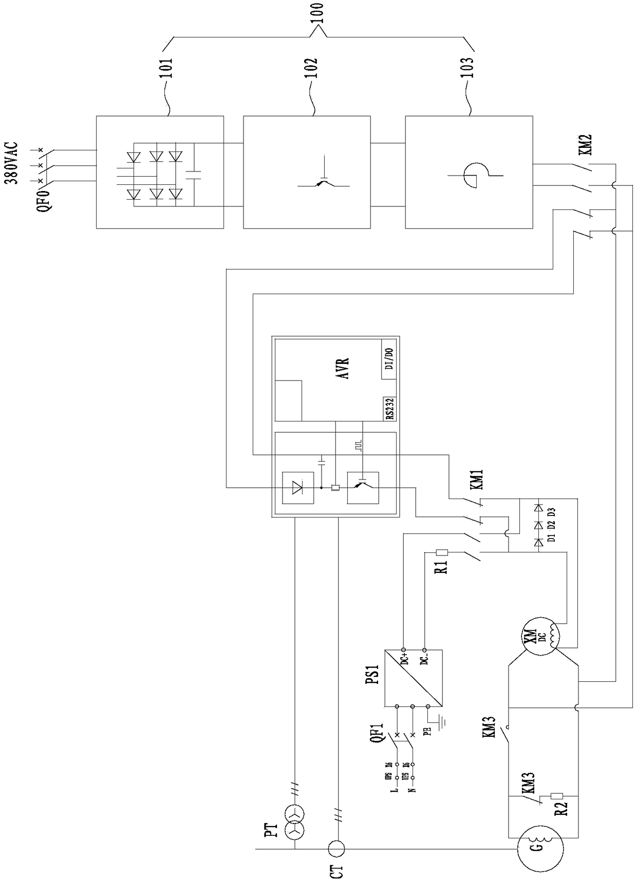
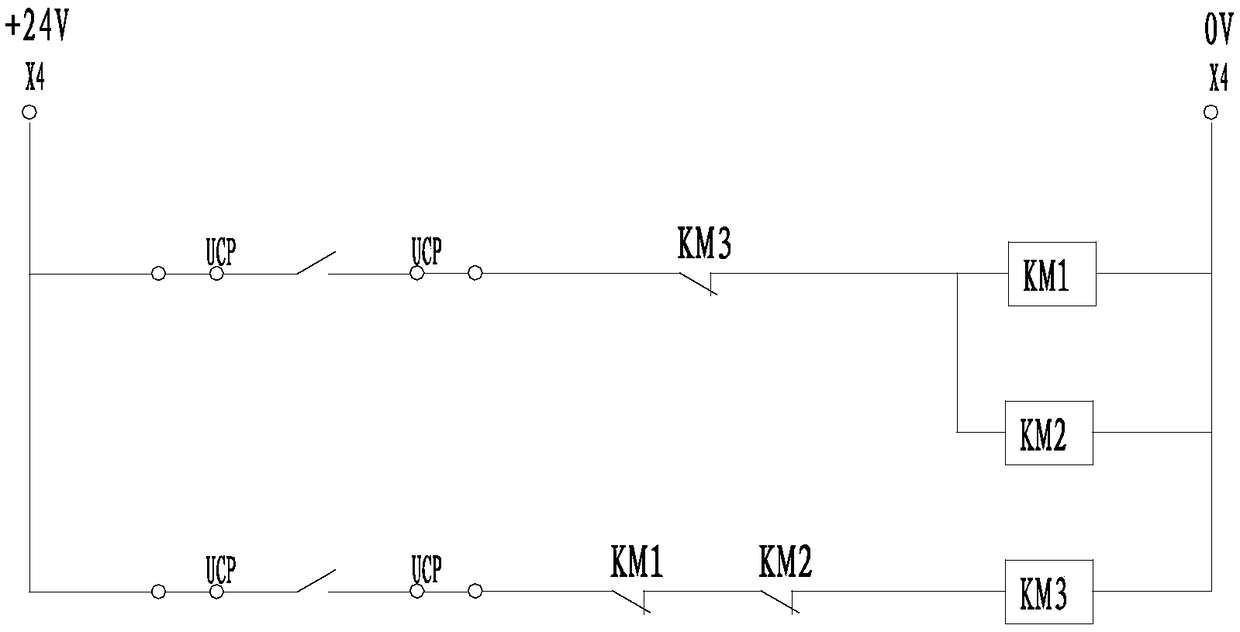
[0030] refer to figure 2 with image 3 , the starting and excitation system of th...
PUM
 Abstract
Description
Claims
Application Information