
Electric movable frame structure

A movable rack and electric drive technology, which is applied in the direction of rotating cabinets, wardrobes, household appliances, etc., can solve the problems of single structure, inconvenience, and storage racks that cannot meet daily use, etc., achieve flexible and convenient storage, and improve user experience.

Inactive Publication Date: 2019-01-29
ULIKE
View PDF10 Cites 0 Cited by
  • Summary
  • Abstract
  • Description
  • Claims
  • Application Information

AI Technical Summary

Problems solved by technology

[0002] Items often used by modern people such as: sports shoes, badminton shoes, badminton rackets, shuttlecocks, daily wear items such as: shoes, shoe handles, hats, umbrellas, parasols, irons, ironing racks, children's toys, household maintenance tools such as: There are more and more products such as screwdrivers, wrenches, flashlights, and vacuum cleaners. These products need to be properly stored; however, the existing storage racks are often not suitable for daily use, and the structure is single and fixed, which has limitations.
[0003] In summary, the existing methods obviously have inconvenience and defects in actual use, so it is necessary to improve them

Method used


Image

  • Electric movable frame structure
  • Electric movable frame structure
  • Electric movable frame structure

Examples


Embodiment Construction

[0029] In order to make the object, technical solution and advantages of the present invention clearer, the present invention will be further described in detail below in conjunction with the accompanying drawings and embodiments. It should be understood that the specific embodiments described here are only used to explain the present invention, not to limit the present invention.

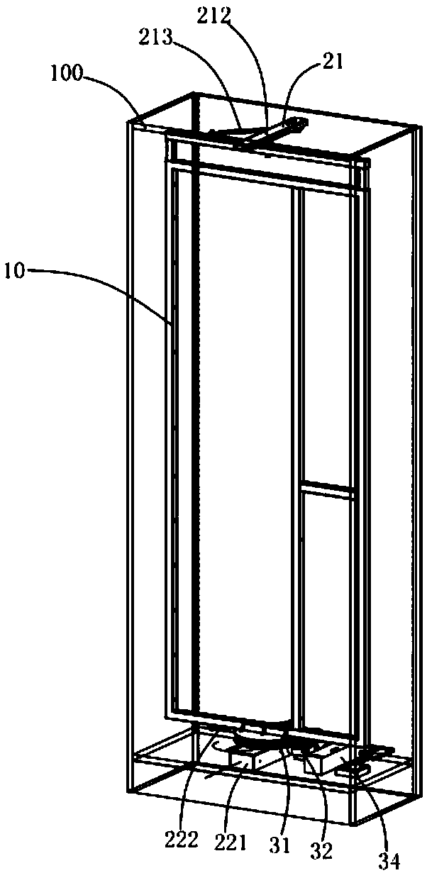
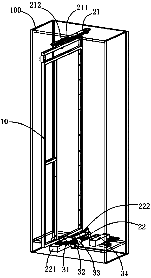
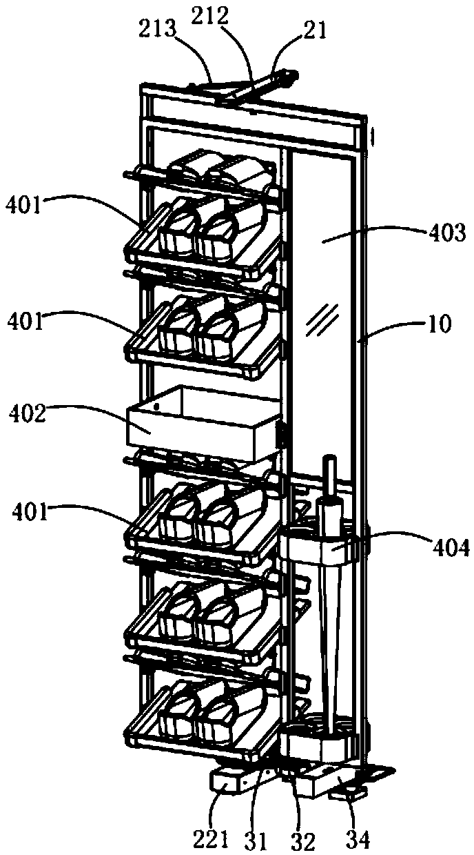
[0030] Figure 1 to Figure 7 It shows the structure of the electric movable frame according to the first embodiment of the present invention, installed in the cabinet body 100, including a vertical frame 10, an upper rail 21, a lower rail 22, a moving mechanism and an electric drive mechanism, the vertical The upper and lower ends of the frame 10 are movably assembled on the upper rail 21 and the lower rail 22 respectively, the moving mechanism is installed on the vertical frame 10, and the electric drive mechanism is connected with the moving mechanism to control the driving of the moving mechanis...


PUM


Abstract

The invention is applicable to the technical field of storage devices, and provides an electric movable frame structure. The electric movable frame structure is mounted in a cabinet, and comprises a vertical framework, an upper rail part, a lower rail part, a moving mechanism and an electric driving mechanism, wherein the upper end and the lower end of the vertical framework are movably assembledto the upper rail part and the lower rail part, the moving mechanism is mounted on the vertical framework, and the electric driving mechanism is connected with the moving mechanism for controlling themoving mechanism to drive the vertical framework to move relative to the upper rail part and the lower rail part. For the electric movable frame structure, the automatic operation can be realized, the storage is more flexible and more convenient, and thus the user experience is promoted.

Description

technical field [0001] The invention relates to the technical field of storage devices, in particular to an electric movable frame structure. Background technique [0002] Items often used by modern people such as: sports shoes, badminton shoes, badminton rackets, shuttlecocks, daily wear items such as: shoes, shoe handles, hats, umbrellas, parasols, irons, ironing racks, children's toys, household maintenance tools such as: There are more and more products such as screwdrivers, wrenches, flashlights, and vacuum cleaners. These products need to be properly stored; however, the existing storage racks are often not suitable for daily use, and the structure is single and fixed, which has limitations. [0003] In summary, the existing methods obviously have inconveniences and defects in actual use, so it is necessary to improve them. Contents of the invention [0004] In view of the above defects, the purpose of the present invention is to provide an electric movable rack str...

Claims


Application Information

Patent Timeline
Patent Type & Authority Applications(China)
IPC IPC(8): A47B49/00A47B61/04
CPCA47B49/004A47B49/008A47B61/04A47B2220/0091
Inventor 杨瑞链
Owner ULIKE
Learn More