Sleeper automatic laying robot for railway emergency rescue and disaster relief
What is Al technical title?
Al technical title is built by PatSnap Al team. It summarizes the technical point description of the patent document.
An automatic laying and robot technology, applied in the direction of laying tracks, roads, tracks, etc., can solve the problems of difficult work of large equipment, poor work continuity, and high labor costs, and achieve the effect of reducing labor costs, high work efficiency, and low labor costs.
Active Publication Date: 2019-01-29
胡佳威
View PDF6 Cites 4 Cited by
Summary
Abstract
Description
Claims
Application Information
AI Technical Summary
This helps you quickly interpret patents by identifying the three key elements:
Problems solved by technology
Method used
Benefits of technology
Problems solved by technology
[0003] In order to make up for the deficiencies in the prior art, the present invention provides an automatic sleeper laying robot for railway rescue and disaster relief. The present invention can solve the problems of high labor cost, low work efficiency, poor work continuity and large If the equipment is difficult to work and other problems, it can realize the function of automatic laying of sleepers, and has the advantages of low labor cost, high work efficiency, high work continuity and small size.
Method used
Image
Click on the blue label to locate the original text in one second.
Reading with bidirectional positioning of images and text.
Examples
Embodiment Construction
[0016] In order to make the technical means, creative features, goals and effects achieved by the present invention easy to understand, the present invention will be further described below in conjunction with specific illustrations.
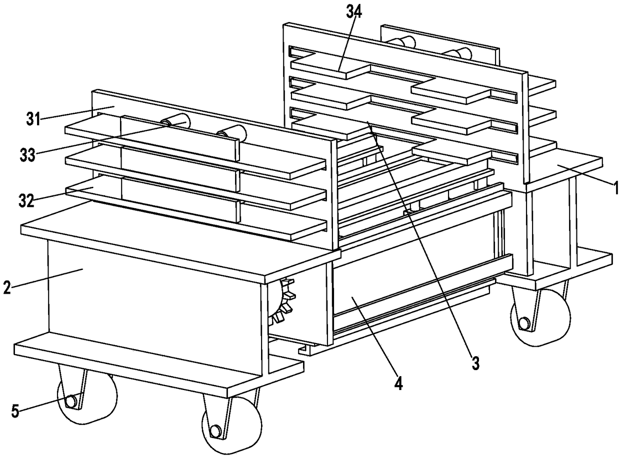
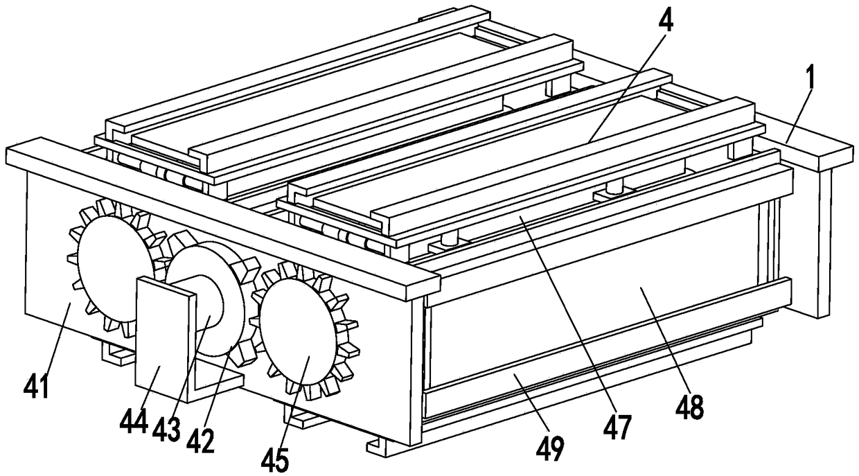
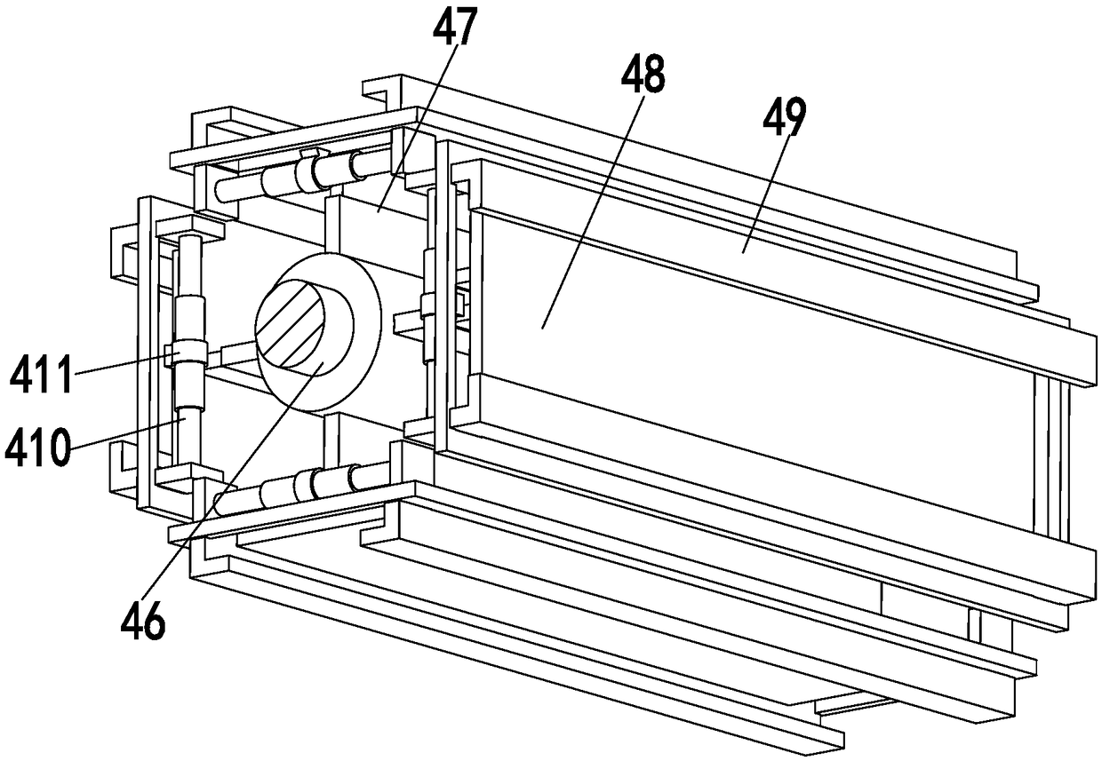
[0017] Such as Figure 1 to Figure 3 As shown, an automatic sleeper laying robot for railway rescue and disaster relief, including a base plate 1, a working frame 2, a storage rack 3, a laying device 4 and a walking wheel 5, the number of the base plates 1 is two, and the two base plates 1 are symmetrically arranged , a working frame 2 is installed at the lower end of the substrate 1, a walking wheel 5 is installed at the lower end of the working frame 2, a storage rack 3 is installed at the upper end of the substrate 1, and a laying device 4 is installed between the two substrates 1; wherein:
[0018] The storage rack 3 includes a mounting plate 31, an adjusting frame 32, an adjusting cylinder 33 and a material placement plate 34, the mounting ...
PUM
Abstract
The invention relates to a sleeper automatic laying robot for railway emergency rescue and disaster relief. The sleeper automatic laying robot comprises two base plates, working frames, storing frames, a laying device and traveling wheels; the two base plates are arranged in a bilateral symmetry mode, and the working frames are mounted at the lower ends of the base plates; the traveling wheels aremounted at the lower ends of the working frames, and the storing frames are mounted at the upper ends of the base plates; the laying device is mounted between the two base plates, and the storing frames comprise mounting plates, adjusting frames, adjusting air cylinders and placing plates; and the laying device comprises a vertical plate, a rotating plate, a rotating motor, a mounting frame, a rotating gear, a rotating tube, a telescopic supporting plate, a bearing plate, a fixing plate, a fixing electric push rod and a fixing ring. The problems that in the existing process of sleeper layingfor railway emergency rescue, the labor cost is high, the working efficiency is low, the work continuity is poor, and large equipment works difficultly can be solved, the function of automatic layingon a sleeper can be achieved, and the sleeper automatic laying robot has the advantages of being low in labor cost, high in working efficiency, high in work continuity, small in size and the like.
Description
technical field [0001] The invention relates to the field of railway emergency rescue and disaster relief equipment, in particular to an automatic laying robot for railway sleeper rescue and disaster relief. Background technique [0002] When encountering natural disasters such as mountain torrents and heavy rains, railways are extremely vulnerable to damage. During the rescue and disaster relief process, it is necessary to repair and replace the damaged part of the railways, including re-laying of sleepers. The current automatic sleeper laying equipment is generally large in size. When the disaster is severe and there is not enough work space, the existing laying equipment cannot work. At this time, the sleeper is often replaced manually. When transporting, it is time-consuming and laborious, and the work efficiency is low, which brings great inconvenience to the normal progress of follow-up disaster relief work. In addition, when laying sleepers manually, the continuity of...
Claims
Application Information
Patent Timeline
Application Date:The date an application was filed.
Publication Date:The date a patent or application was officially published.
First Publication Date:The earliest publication date of a patent with the same application number.
Issue Date:Publication date of the patent grant document.
PCT Entry Date:The Entry date of PCT National Phase.
Estimated Expiry Date:The statutory expiry date of a patent right according to the Patent Law, and it is the longest term of protection that the patent right can achieve without the termination of the patent right due to other reasons(Term extension factor has been taken into account ).
Invalid Date:Actual expiry date is based on effective date or publication date of legal transaction data of invalid patent.