Ultrasonic borehole wall imaging method applied to cylindrical ultrasonic array

An ultrasonic array and imaging method technology, applied in earthwork drilling, wellbore/well components, measurement, etc., can solve problems such as low detection accuracy and complicated board wiring, so as to improve resolution, save the number of channels, and reduce costs and difficult effects

Active Publication Date: 2019-01-29
INST OF ACOUSTICS CHINESE ACAD OF SCI
View PDF5 Cites 6 Cited by
  • Summary
  • Abstract
  • Description
  • Claims
  • Application Information

AI Technical Summary

Problems solved by technology

[0004] The purpose of the present invention is to overcome the technical problems of complex board wiring and low detection accuracy in the existing phased array imaging technology. The present invention provides an ultrasonic wellbore imaging method applied to a cylindrical ultrasonic array. The method Applied to ultrasonic wellbore imaging detection, it will greatly reduce the number of independent channels of the cylindrical array ultrasonic wellbore imaging system, reduce the hardware cost of the system, and avoid the circuit board of the ultrasonic wellbore imaging system due to the limited space in the underground Complex wiring and system instability

Method used


Image

  • Ultrasonic borehole wall imaging method applied to cylindrical ultrasonic array
  • Ultrasonic borehole wall imaging method applied to cylindrical ultrasonic array
  • Ultrasonic borehole wall imaging method applied to cylindrical ultrasonic array

Examples


Embodiment 1

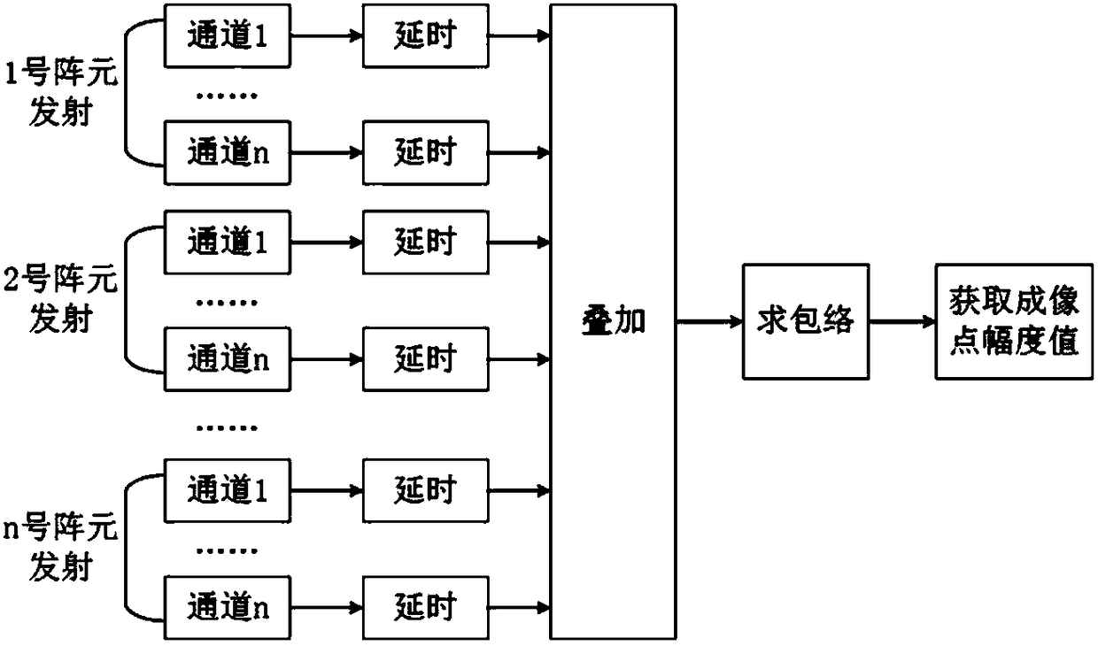
[0040] In this example, the workflow of ultrasonic wellbore imaging using the synthetic aperture focusing method specifically includes the following two operations:

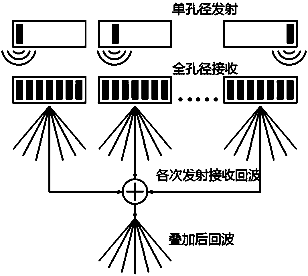
[0041] (1) Complete the control of ultrasonic transmission and echo reception and the acquisition of original echo signals for the current dynamic array element group. During this process, the system control workflow is as follows: figure 2 shown. There are a total of n array elements in the dynamic array element group. For the first time, array element 1 transmits ultrasonic signals, and array elements 1 to n (that is, full aperture) receive echo signals, and array element 2 transmits ultrasonic signals for the second time. , the full aperture receives the echo signal, and so on, until the nth time the last array element transmits the ultrasonic signal, and the full aperture receives the echo signal. The echo signal set obtained by the current dynamic array element group contains the combination relationship o...


PUM


Abstract

The invention relates to an ultrasonic borehole wall imaging method applied to a cylindrical ultrasonic array. The method comprises: step 1) driving each transducer array element in the cylindrical ultrasonic array, sequentially transmitting ultrasonic signals separately, all transducer array elements receiving echo signals corresponding to each transmitted signal at the same time; step 2) using the echo signals obtained in step 1), performing point-by-point focusing imaging processing on each imaging point according to a synthetic aperture focusing algorithm, to obtain echo amplitude data corresponding to each imaging point; and step 3) splicing the echo amplitude data corresponding to each imaging point, to obtain an amplitude imaging image in an entire imaging plane. The ultrasonic wellbore wall imaging method is applied in ultrasonic borehole wall detection, and would greatly reduce the number of independent channels of the cylindrical array ultrasonic borehole wall imaging system,reduce hardware cost of a system, and the method can improve resolution ratio of borehole wall imaging detection under the condition that the frequency of a downhole transducer is low.

Description

technical field [0001] The invention relates to the technical field of ultrasonic wellbore imaging, in particular to an ultrasonic wellbore imaging method applied to a cylindrical ultrasonic array. Background technique [0002] Ultrasonic borehole wall imaging detection technology uses the amplitude information extracted from the reflected echo of the borehole wall or casing wall to clearly and intuitively display the condition of the borehole wall in the form of an echo amplitude map. Compared with the traditional ultrasonic borehole wall imaging detection technology, the cylindrical array ultrasonic borehole wall imaging detection technology has the advantages of avoiding probe rotation and adjustable focus point, and has received extensive attention in recent years. The existing cylindrical array ultrasonic borehole wall imaging adopts phased array imaging technology. By controlling the transmission and reception delays of each independent channel, the emission beam of th...

Claims


Application Information

Patent Timeline
Patent Type & Authority Applications(China)
IPC IPC(8): E21B47/002E21B47/14E21B49/00
CPCE21B47/002E21B47/14E21B49/00
Inventor 董晗张碧星
Owner INST OF ACOUSTICS CHINESE ACAD OF SCI
Why Eureka
Try Eureka